TM-5-4310-389-14
3.
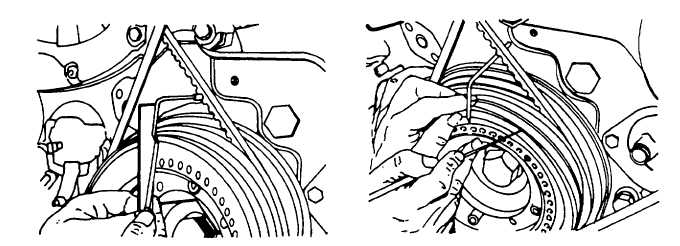
Turn back crankshaft through about one revolution of gauge pointer, then again in original direction up to 0.1 mm
(10 graduations) from 0 position. Provide a mark on the V-belt pulley agreeing with dowel sleeve (figure 4-49).
4.
Turn crankshaft in running direction beyond 0 through about one revolution of the gauge and turn back up to 0.1
mm (10 graduations) before 0. Provide second mark on belt pulley.
5.
Measure and mark the half-way position between the two marks (figure 4-50).
NOTE
The midway mark will be the dead center mark. When it is opposite the retainer sleeve, cylinder 1
will be in the top dead center position.
6.
Remove the two oil cooler bolts that secure the engine throttle stop to the cooler.
7.
Remove ten bolts and nuts.
8.
Remove pump.
9.
Remove bolts of starting crank bearing and remove bearing (figure 4-51).
10.
Unscrew hex head socket screws from the starting crank and remove.
11.
Remove two diagonally located screws securing the gear wheel on the camshaft.
12.
In place of these two screws, assemble two, 8 mm diameter x 80 mm jacking screws and slacken the other two
screws.
Figure 4-49. Setting Gauge Pointer
Figure 4-50. Measuring and Making
Halfway Points
4-73


