TM-5-4310-389-14
6.
To reinstall the governor assembly, apply grease on sleeve before installing.
7.
Install governor assembly, ensuring control lever seats against sleeve.
8.
Reinstall fuel adjustment cap assembly and turn in four threads.
9.
Reinstall C clip. Tighten fuel adjustment cap assembly.
b.
Plunger and Barrel Disassembly.
CAUTION
Roller and tappet assembly is spring-loaded. Use caution when removing tappet body nuts.
1.
Remove tappet body nuts. Remove body and tappet assembly (figure 5-85).
WARNING
Fuel timing shims are matched to each pump assembly. Do not interchange shims, barrels, plungers,
or metering valves. Serious damage or personnel injury may occur.
2.
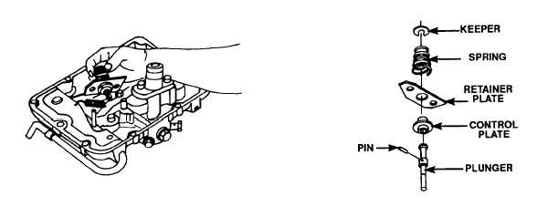
Remove plunger and control panel assembly
Figure 5-85. Assembled Plunger and
Figure 5-86. Disassembled Plunger and
Metering Sleeve
Metering Sleeve
5-57

