TM-5-4310-389-14
2.
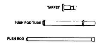
Ensure rods are straight and the oil hole is free of obstruction.
3.
Ensure tubes are straight and free from defects.
4.
Ensure tappets are not worn and oil hole is free of obstruction. Replace parts, as required.
b.
Checking Push Rods, Push Rod Tubes, and Tappets.
1.
Dismantle bracket (7, figure 5-83).
2.
Replace any worn parts.
3.
Press in bearing bushing (2); ensure the lubrication oil holes are in alignment.
NOTE FOR REFITMENT
The rocker arms (3) are provided with an oil metering screw (4), the chamfered face of which should
point to the thrust pad (6). Check that one thread turn of the screw projects beyond the locknut (5).
When the screw is finally adjusted under idling conditions on the engine test bench or in a vehicle, the
position of the chamfered face is irrelevant. All you have to ensure is that a small oil flow toward the
thrust pad is still visible.
Figure 5-83. Rocker Arm Bracket Assembly
5-53

