TM 5-4310-393-14
adjust tension on the V-belt (see paragraph 3-14.2). When engine and compressor are in proper alignment, and V-belt
tension is correct, retighten the hold down bolts.
4-13.2. ENGINE CYLINDER HEAD AND VALVE ASSEMBLY.
This task covers: A. Inspect B. Adjust C. Check
D. Install
Tools:
Materials/Parts:
Tool Kit, General Mechanic's Set
Valve Cover Gasket (PIN 03208902
Torque Wrench
Equipment Conditions:
Engine Unit Shut Down and cold
A.
Inspect.
1.
Checking the Tappet Clearance.
a.
Rotate decompression lever clock-
wise until audible click is heard.
b.
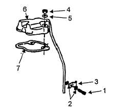
Loosen the screw (1) securing the
valve cover vent line clamp (3) with an open end wrench
(see figure 4-1).
c.
Remove valve cover retaining nuts
(4), and washers (5) lift off valve cover (6) and gasket
(7).
d.
Using the hand crank, turn engine
slowly in the direction of rotation until compression
resistance Is felt.
e.
Using a 0 004 inch (0.10mm) feeler
gauge, measure distance between rocker arm and valve
stem
f.
Tappet clearance is correct when
this measurement is 0.004 inch (0.10mm) when engine
is cold and there is a slight drag felt on the feeler gauge.
B.
Adjust.
1.
Adjusting
the
Tappet
Clearance
and
Decompression Mechanism.
a.
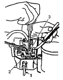
Put decompression lever (Figure 4-
2, Item 1) in the RUN position. See figure 4-3.
b.
Turn engine clockwise when facing
throttle control lever until compression resistance can be
felt.
Figure 4-1. Removing Valve Cover
Figure 4-2. Tappet Adjustment
4-12


