TM 5-4310-393-14
Compressor Impeller/Groove Pulley) are also provided for the compressed air. Each of these units is replaced by
unbolting the affected part and replacing it with a manufacturer's numbered part.
4-14.2. LUBRICATING SYSTEM
This task covers: A. Inspect B. Repair C. Replace
Tools:
Materials/Parts:
Tool Kit, General Mechanic's Set
O-ring (P/N N07091)
Calibrated Test Pressure Gauge
Halo Carbon Grease, NSN 9150-00-754-2760
Equipment Conditions
Compressor Removed and Secured
NOTE
The compressor oil pump is a non-repairable item. Inspection and venting of the
pump are described in paragraph 3-14.1. In case the pump becomes inoperable,
replace it as follows:
A.
Replace.
1.
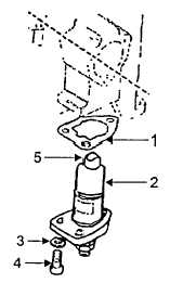
Replacing the Lube Oil Pump (Figure 4-6).
a.
Remove oil line from bottom of oil
pump.
b.
Remove three cap screws (4) and
washers (3).
c.
Remove oil pump (2) and gasket (1)
from compressor crankcase.
d.
Replace pump with a new one in
reverse order of removal.
e.
Remove the filter mount (figure 3-7
item 14) from the crankcase pump housing to provide
access to the pump drive cam.
Figure 4-6. Oil Pump
f.
The actuator (5) of the pump must always be in contact with the cam.
g.
Put a 0 018 inch (0.3 mm) feeler gauge between the pump actuator (5) and the low side of cam.
h.
Turn the fan wheel by hand This should be possible without heavy resistance.
i.
If heavy resistance is felt, install a new gasket of proper thickness. The pump actuator must always
be in contact with the cam, but must not overstroke the pump.
j.
Reassemble removed components as original.
B.
Inspect.
1.
Inspecting the Oil Pressure Regulator.
a.
The lube oil pressure regulator is mounted on the third stage cylinder of the compressor. Oil from the
lube oil pump enters the regulator at a port in the mounting flange. Oil returns to the crankcase from the regulator through
4-16