TM 5-4310-451-14
1-14. AIR COMPRESSOR ASSEMBLY (Con’t).
(6)
After the oil passes through the thermal valve (3), it is directed through the main oil filter (6) where it is
filtered. The filter has a replaceable filter element and a built-in bypass valve. The bypass valve allows the oil to flow even
when the filter element becomes plugged and requires changing or when viscosity of the oil is too high for adequate flow.
(7)
After the oil is properly filtered, it flows through the oil stop valve (7). The oil stop valve functions on
shutdown when it shuts off the oil supply to the air compressor (2). The oil stop valve is held open by a pressure signal
from the air compressor. At shutdown the pressure signal is lost and the oil stop valve closes, isolating the air compressor
from the cooling system.
(8)
A portion of the oil flowing to the air compressor (2) is routed to a bearing oil filter (8). All oil flowing to the
gears, shaft seal, and internal bearings of the air compressor flows through this extra-fine filter ensuring the cleanest
possible oil for these components. This filter also has a built-in bypass valve and a replaceable filter element.
c.
Discharge System.
(1)
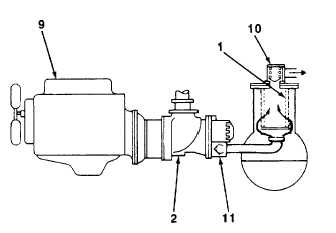
The air compressor (2), which uses a
separate oil system from the engine (9), discharges a
compressed air/oil mixture through a compressor dis-
charge check valve (11) into the oil separator (1). The
dis- charge check valve prevents discharged air from
returning to the compression chamber after shutdown.
(2)
From the compressor discharge check
valve (11), the air/oil mixture Is directed to the oil
separator (1). The oil separator has three functions:
(a)
Acts as a primary oil separator.
(b)
Serves as the air compressor oil separator.
(c)
Houses the final oil separator.
(3)
The compressed air/oil mixture enters the oil separator (1) and is directed against the side wall. By change
of direction and reduction of velocity, large droplets of oil fall to the bottom of the oil separator. The small percent of oil
remaining in the compressed air collects on the surface of the final separator element as the compressed airflows through
the separator. As more and more oil collects on the element surface, the oil descends to the bottom of the oil separator.
A return line (or scavenge tube) leads from the bottom of the final separator element of the inlet region of the air
compressor (2). Oil collecting on the bottom of the final separator element is returned to the air compressor by the
pressure difference between the area surrounding the final separator element and the air compressor inlet. An opening,
protected by a strainer, is included in this return line to ensure proper flow.
(4)
The oil separator (1) is rated at 150 psi (1034 kPa) working pressure. A minimum pressure valve (10),
located downstream from the oil separator, ensures a minimum receiver pressure of 40 psi (276 kPa) during all conditions.
This pressure is necessary for proper air/oil separation and proper oil circulation.
(5)
A check valve at the outlet of the receiver is installed to prevent compressed air in the service line from
bleeding back into the receiver on shutdown when the air compressor unit is being run In parallel with other air compressor
units tied to large air system. The check valve is also necessary when the air compressor unit is functioning with a
pressure pot sandblasting operation.
TA704681
1-15


