TM 5-4310-451-14
1-14. AIR COMPRESSOR ASSEMBLY (Con’t).
(6)
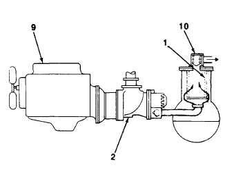
A safety relief valve, located within the separator
discharge check valve (12), is set to open if the oil
separator (1) pressure exceeds 140 psi (965 kPa). A
temperature switch will shut down the air compressor
unit if the discharge temperature reaches 240°F
(116°0C).
(7) Oil is added to the oil separator (1) through a
capped oil filler. An oil level gage enables the operator
to visually monitor the oil separator oil level.
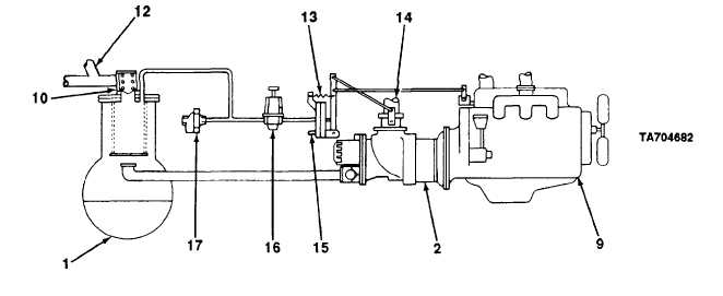
d. Control System. The purpose of the control system is to regulate the amount of air intake In accordance with the
amount of compressed air being used. The control system consists of a sullicon control (13), pressure regulating valve
(16), blowdown valve (17), and link rods which connect the sullicon control to the inlet valve (14) and engine (9) governor.
(1) During startup the pressure regulating valve (16) and the sullicon control (13) are Inoperative. When the air
compressor unit is started, the oil separator (1) pressure will quickly rise from 0 to 40 psi (0 to 276 kPa). The spring on the
sulllcon control holds the butterfly valve fully open and the air compressor assembly operates at full rated capacity. As the
air compressor assembly operates at full capacity, the engine (9) runs at full speed. The rising oil separator pressure is
Isolated from the service line by the minimum pressure valve (10) which is set at approximately 40 psi (276 kPa).
(2) When the oil separator (1) pressure rises above 40 psi (276 kPa), the minimum pressure valve (10) opens and
delivers compressed air to the service line. The sullicon control (13) remains inoperative, holding the inlet
valve (14)
fully open for maximum air output. The engine (9) will continue to run at full speed.
1-16


