TM 5-4310-451-14
1-14. AIR COMPRESSOR ASSEMBLY (Con’t).
(3)
If less than the rated capacity of air is required, the service line pressure will rise above 100 psi (690 kPa). The
pressure regulating valve (16) gradually opens, applying pressure to the diaphragms on the sullicon control (13). This
causes the sullicon control to partially close the inlet valve (14) and reduce the speed of the engine (9). As the pressure
increases, the sullicon control will further close the inlet valve and continue reducing the engine speed until it reaches
loaded speed. The sullicon control has an opening (15) in its cover which vents a small amount of air to the atmosphere
when the pressure regulating valve is open. This allows the sullicon control to vary air output matching air demand. The
opening also bleeds any accumulated moisture from the sullicon control. The air compressor assembly will continue to run
in this manner until air demand increases. As air demand increases, pressure in the oil separator (1) will fall below 100 psi
(690 kPa). The pressure regulating valve will close, the inlet valve will be fully open, and the engine will once again run at
full speed.
(4)
The blowdown valve (17) is held closed by a pressure signal from the air compressor (2). Upon shutdown, the
pressure signal is lost and the blowdown valve opens venting oil separator pressure to the atmosphere.
e.
Air Inlet System.
(1)
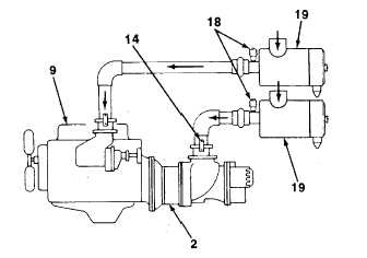
The air inlet system consists of two air cleaners
(19) and restriction indicators (18), an air inlet valve (14),
and interconnecting piping to the engine (9) and air
compressor assembly.
(2)
The air inlet valve (14) controls the amount of air
intake to the air compressor (2) in response to the
operation of the sullicon control (see subpara graph d).
(3)
The air cleaners (19) are three-stage dry
element type filters. These filters are capable of cleaning
extremely dirty air; however, in such cases more
frequent checks of the restriction Indicators (18) will be
required. The restriction indicator will be red when re-
striction of air passing through the air cleaner becomes
too high.
f.
Instrument Panel Group. The instrument panel group consists of a panel containing an engine coolant
temperature gage, engine oil pressure gage, air pressure gage, air compressor discharge temperature gage, ammeter,
tach/hourmeter, ON/OFF engine switch, engine start button, override button, emergency stop control which is located on
the outside just below the instrument panel window, a cold start valve, fuse, and ether starting aid kit.
g.
Electrical System.
(1)
Refer to the wiring diagram in paragraph 4-61 for the location of major components of the electrical system.
(2)
The electrical system is comprised of not only the necessary equipment required to operate the air compressor
unit, but also a system to shut down the air compressor unit in the event of a malfunction.
(3)
The components of the electrical system are:
(a)
Engine starter with an integral solenoid.
(b)
Two batteries.
TA704683
1-17


