TM 5-4310-451-14
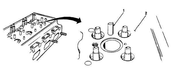
5-22. VALVE BRIDGE GUIDE PINS REPLACEMENT.
This Task Covers:
a.
Removal
b.
Installation
Initial Setup:
Equipment Conditions:
Tools/Test Equipment:
áFuel injectors removed (see paragraph 5-57).
áField automotive shop set
áExhaust valves removed (see paragraph 5-24).
áValve bridge guide installer, J7482
a. REMOVAL
NOTE
áAll twelve valve bridge guide pins are removed same way. This procedure covers one guide pin.
áIf replacing defective guide pin, perform steps 1 through 4. If replacing broken off guide pin,
perform step 5.
1.
File two notches Y1 in. (1.59 mm) deep about 1X in. (3.81 cm) from top of guide pin (1).
2.
Install remover over guide pin (1) and aline two setscrews in remover with notches in guide pin. Tighten
setscrews.
3.
Install long spacer over remover.
4.
Thread nut on remover and turn clockwise to remove guide pin (1) from cylinder head (2).
5.
Center punch guide pin (1) and drill a hole using no. 3 (0.213 in.) drill bit.
6.
Thread remover into guide pin (1) and remove guide pin from cylinder head (2).
5-39


