TM 5-4310-451-14
5-25. CAM FOLLOWER ASSEMBLY AND PUSHROD REPLACEMENT (Con’t).
7.
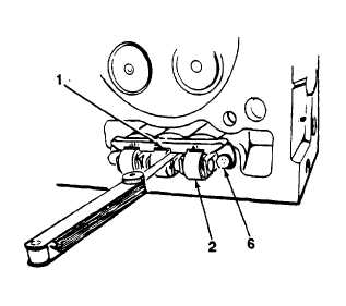
Insert feeler gage between cam follower assem-
bly (2) and legs of guide (1). Clearance between
legs of guide and cam follower assembly should
be 0.005 in. (0.127 mm).
8.
If clearance is less than 0.005 in. (0.127 mm),
loosen two screws (6), adjust position of guide
(1), and repeat steps 6 and 7.
FOLLOW-ON TASKS:
Install rocker arms (see paragraph 5-41).
Install cylinder head (see paragraph 5-28).
5-49

