1
Inclosure door
8
Heater fuel filter
14
Lower accessory drawer
2
Lifting ring sockets
9
Center toolbox
15
Upper accessory drawer
3
Lifting ring
10
Engine exhaust director
16
Battery box
4
Air compressor
11
Hand lift handle
17
Air line coupler
5
Drum adapter
12
Lifting capacity plate
18
Air tank draincock
6
Heater
13
Tie-down rings
19
Reel bank assembly
7
Heater control panel
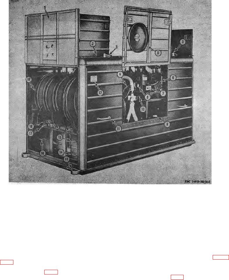
Figure 2. Lubricating unit, left three-quarter view.
at freezing temperatures. An engine exhaust hose
respective lubricant storage compartments.
Air
conducts engine exhaust gases into a heat reservoir
pressure and speed of each pump is controlled by
under the bottom of the storage compartment for
separate air pressure regulators and pressure is
registered with an air pressure gage (12, fig. 1)
(10, fig. 2) diverts exhaust gases through a hose to the
attached to each regulator. The pumps will operate at
atmosphere when heating of lubricant is not necessary.
air pressures ranging from 20 psi to 200 psi.
The alcohol dispenser (9, fig. 6) prevents freezing of
The gasoline engine (5) and the gasoline engine
condensed air in air lines during cold weather operation.
powered air compressor (4, fig. 2) are mounted on
Three air-powered pumps are mounted in their
4

