
Section III. CONTROLS AND INSTRUMENTS
16. General
18. Ammeter
This section describes, locates, illustrates, and furnishes
The ammeter (1, fig. 6) is located on the engine control
the operator, or crew, sufficient information pertaining to
box. It is a dial-type instrument %which shows if the
the various controls and instruments, provided for the
generator is properly charging or the battery
proper operation of the lubricating unit.
discharging. The indicator will be just past the 0 mark
on the charge side when operating properly.
17. Stop Button Switch
19. Starter Button Switch
The stop button switch (3, fig. 6) is a pushbutton control
switch located on the engine control box. The button is
The starter button switch (2, fig. 6) is a push button
pushed in to stop the engine.
control switch located on the engine control
1
8
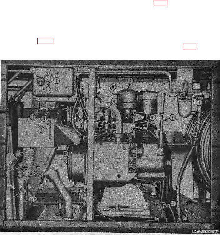
Engine clutch lever
14
Fire extinguisher
2
Start button switch
9
Alcohol dispenser
15
Transfer pump
3
Stop button switch
10
Belt guard bracket
16
Lubricant container hot air damper
4
Crankcase breather
11
Engine fuel filter
17
Engine hot air damper
5
Air heater duct
12
Heater duct
18
Choke control
6
Engine air cleaner
13
Fuel tank filler pipe
19
Idle control
7
Speed reduction shutoff cock
Figure 6. Lubricating unit controls and instruments, engine side.
17