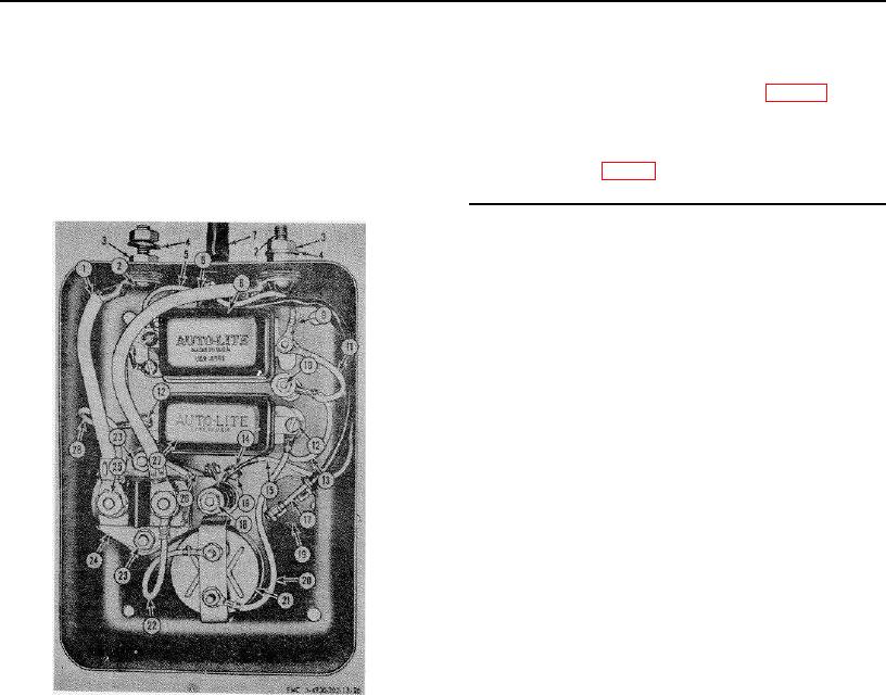
1
Exhaust pipe
13
Terminal cable, control box-to-battery
2
Cap nut, 1/4--20 (4 rqr)
14
Terminal connection strip
3
Cap screw, 1/4--20 x 1/2 in. lg (4 rqr)
15
Terminal cable, control box-to-starter-generator
4
16
Choke control
5
Screw, 1/4-28 x 1 1/2 in. lg (2 rqr)
17
Heat duct
6
Screw, 1/4-28 x 2 1/2 in. lg
18
Idle control
7
Stop button
19
Heat damper box
8
Start button
20
Engine hot air damper control
9
Bolt, ,3/16-32 x 1/2 in. lg (2 rqr)
21
Engine hot air damper control
10
Bolt, 1/8-36 x 2 1/4 in. lg
22
Exhaust outlet
11
Screw, 1/8-36 x 3/4 in. lg (2 rqr)
23
Control box
12
Terminal nut, 5/16-18 (4 rqr)
24
Mounting plate
Figure 25-Continued.
(7) Disconnect the fixed resistor-to-voltage
(3) Disconnect
the
ammeter-to-voltage
regulator lead (13) at the voltage regulator
regulator lead (20) at the ammeter (21),
(27) and at the fixed resistor (10).
and at the voltage regulator (27).
(8) Remove the two bolts (9, fig. 25) which
(4) Disconnect the ammeter-to-starter button
secure the voltage regulator to the control
lead (22) at the ammeter (21), and at the
box, and remove the voltage regulator.
starter switch (24).
(9) Disconnect the relay-to-fixed resistor lead
(5) Remove the two screws which secure the
(11, fig. 26) at the fixed resistor
ammeter (21) to the control box, and
remove the ammeter.
1
Lead, start button-to-terminal screw
2
Screw, 5/16-18 x 1/4 in. lg (2 rqr)
3
Nut, terminal, 5/16-18 (4 rqr)
4
Flat washer, 5/16 in. (2 rqr)
5
Reverse-current relay lead
6
Lead, starter switch-to-terminal screw
7
Harness assembly cover
8
Relay, reverse-current
9
Lead, relay-to-starter-generator
10
Resistor, 2 in. x 9/16 in., 50 ohm, 25 watt
11
Lead, relay-to-fixed resistor
12
Screw, 3/16-32 x 1/4 in. lg (3 rqr)
13
Lead, fixed resistor-to-voltage regulator
14
Screw,1/8-32 x 1/4 in. lg (3 rqr)
15
Lead, relay-to-field resistor
16
Nut, 1/8-32 (2 rqr)
17
Ground wire, stop switch-to-magneto
18
Resistor, 1 1/2 in. x 1/2 in., 60 ohm, 10 watt
19
Stop switch
20
Lead, voltage regulator-to-an meter
21
Ammeter
22
Lead, ammeter-to-start button
23
Nut, 1/4-20 (2 rqr)
24
Starter switch
25
Nut, 5/16-18 (2 rqr)
26
Lead, fixed resistor-to-relay
27
Voltage regulator
28
Lead, starter switch-to-voltage regulator
(6) Disconnect the starter switch-to-voltage
regulator lead (28) at the starter switch
(24) and at the voltage regulator (27).
Figure 26. Control box disassembly.
61

