
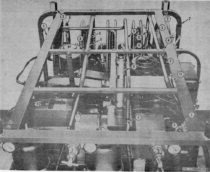
1
Straight frame
5
Grease supply tube
8 U-bolt, /4-20 (7 rqr)
2
Lift ring sockets (4 rqr)
6
Lubricant hose
9 Exhaust pipe
3
Grease manifold assembly
7
U-frame
10 Air line
4
Nut, 1/4-20 (14 rqr)
Figure 38. Lubricant supply tube removal.
(5)
Install the adapter (4) to the reel hub, and
d. Hose Reel Installation.
the adapter (12) to the hose reels (1).
(1) Position the reel pedestals (8) on the reel
e. Reel Bank Installation.
bank channel (10) and install the screws (9)
which secure the reel pedestals to the reel
(1) Install the reel bank assembly on the
bank channel.
lubricating unit.
(2) Position the hose reel (1) on the reel
(2) Install four nuts (11) and four cap screws (9)
pedestals, and position the yoke (6) on the
and lockwashers which secures the reel bank
reel hub.
assembly to the lubricating unit.
(3) Install the hex screws (5) and nuts (7) which
(3) Install the five hoses (13) on the hose reels
secure the yoke over the reel shaft and to
(1).
the reel pedestals (8).
(4) Install the five lubricant hoses (2) one
(4) Tighten the setscrew (3) on the reel shaft.
79