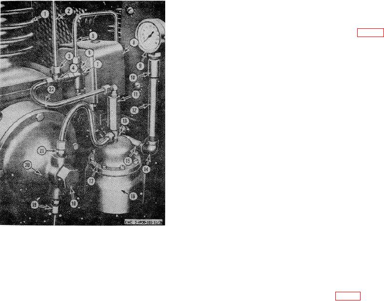
137. Air Pressure Gage
a. Removal.
(1) Remove the air pressure gage (9, fig. 36)
from the pipe coupling (10).
(2) Remove the pipe coupling from the nipple
(12), and the nipple from the elbow (14).
(3) Remove the elbow from the straight
fitting, and the straight fitting from the
manifold.
b. Cleaning, Inspection, and Repair.
(1) Clean all parts, using an approved
cleaning solvent.
(2) Inspect the air pressure gage. See that
the air gage needle is not bent, that the
glass is not cracked or broken, and that
the case is undamaged.
Replace a
defective air pressure gage.
(3) Inspect all parts for bends, dents, cracks,
internal obstructions, or external wear.
Replace any defective parts.
c. Installation.
(1) Install the straight fitting in t he manifold.
(2) Install the elbow (14) in the straight fitting
and the nipple (12) to the elbow.
1
Cylinder
(3) Install the pipe coupling (10) into the
2
Throttle control air tube
nipple, and the air pressure gage (9) into
3
Connector
the pipe coupling.
4
Compression tee
(4) Test the air pressure gage line for leaks.
5
Tank control valve air tube
6
Two-way release valve
7
Screw, 1/4--28 x 3/8 in. (2 rqr)
138. Auxiliary Unloader Release Valve
8
Pressure switch
a. Removal.
9
Air pressure gage
(1) Disconnect the air tube (22, fig. 36) at the
10
Pipe coupling, 1/4 in. NPT
compression tee (4) and at the auxiliary
11
Auxiliary air release valve
unloader release valve (11).
12
Nipple, 1/4 in. NPT x 5 in.
13
Tee
(2) Disconnect the tubing (17) at the unloader
14
Elbow, 1/4 in. 90
cap (20) and at the tee (13).
15
Nipple, 3/8 x 3 1/2, in.
(3) Remove the elbow (23) from the auxiliary
16
Auxiliary unloader assembly
unloader release valve (11).
17
Tubing, 1/4 x 12 in.
(4) Remove the auxiliary unloader release
18
Unloading valve cap
valve from the auxiliary unloader
19
Bleeder tube
assembly (16).
20
Unloading cap
21
Straight connector
b. Cleaning, Inspection, and Repair.
22
Air tube
(1) Clean all parts, using an approved
23
Elbow
cleaning solvent.
Figure 36. Compressor air controls.
(2) Inspect the auxiliary unloader release
valve. If any parts are worn or defective,
(2) and the auxiliary release valve air tube
replace the auxiliary unloader release
(22) to the compression tee.
valve.
(4) Connect the tank control valve air tube (5)
to the two-way release valve.
76

