
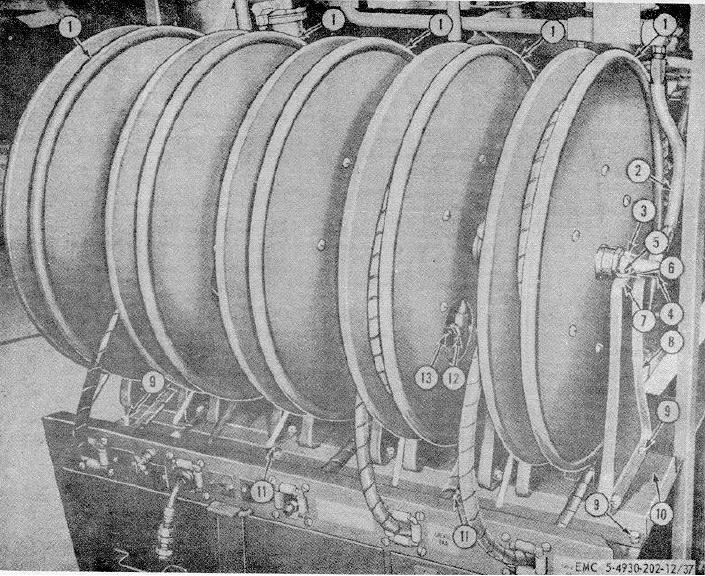
1
Hose reels
6
Yoke
10
Reel bank channel
2
Lubricant hose, 11/32 ID x 15 in.
7
Nut, 5/16--18 (20 rqr)
11
Hex nut, 3/8--16 (4 rqr)
3
Setscrew, 1/4--20 x 3/8 in. lg (10 rqr)
8
Reel pedestal
12
Adapter
4
Adapter, 90 union, 3/8 x 3/8 in.
9
Screw, 3/8--16 x 3/4 in. lg (24 rqr)
13
Hose
5
Hex screw, 5/16--18 x 1 in. lg (20 rqr)
Figure 37. Reel bank and hose reel removal.
c. Cleaning, Inspection, and Repair.
pedestal (8), which secure each hose reel
(1) to the reel bank channel (10).
(1) Clean parts with an approved cleaning
(2)
Remove the adapter (4), one on each
solvent.
hose reel (1), from the reel bank
(2) Inspect each hose for breaks, cuts, or
assembly.
other defects. Replace a defective hose.
(3)
Remove the adapter (12) from the hose
(3) Inspect each hose fitting for damaged
reel (1).
threads, cracks, or other defects. Replace
(4)
Remove the two screws (5), and nuts (7)
damaged fittings.
which secure the yoke (6) to the reel
(4) Inspect each hose reel and swivel for
pedestal (8).
external damage or binding. Replace a
(5)
Remove the hose reel (1), yoke (6), and
defective hose reel or swivel.
the reel pedestal (8) from the reel bank
(5) Paint all exposed metal surfaces on the
assembly.
reel bank assembly.
78