TM 5-4930-218-14
(2) Operation.
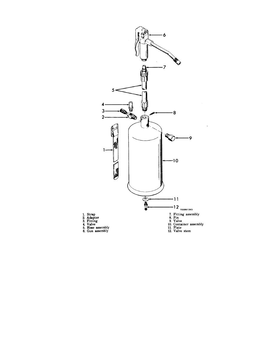
(c) Fill the lubricator with grease until the in-
dicator valve (4) indicates that the lubricator is full.
(a) With the lubricator empty of grease,
remove the valve cap from the valve stem (12) located
Do not overfill.
on the bottom of the tank. Charge the tank to 40 psi
(d) Insert other end of hose (5) into the body of
of air pressure.
the booster valve and screw the swivel fitting assem-
(b) Remove pin (8) and insert hose assembly (5)
bly (7) hand tight.
into connector as far as it will go. Replace pin (8) to
(e) Open the air relief valve on the booster
its full length and check to be sure hose assembly (5)
valve until grease flows in a steady stream. Close the
fits tightly in connector.
relief valve. The unit is now ready for use.


