the speed droop from no load to full load. For this reason, a satisfactory governor setting must be a
compromise between stability and speed regulation.
(3) After the governor is set so that there is no hunting, tighten the adjusting nuts.
Section XI. AIR RECEIVER AND AFTERCOOLER
111. Description
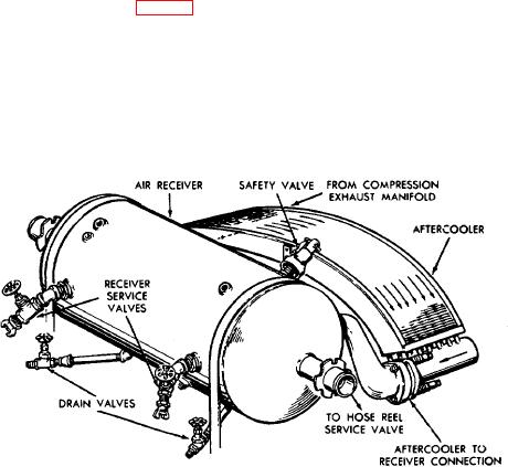
The air receiver has a volumetric capacity of 6 cubic feet. It is mounted above the engine-compressor fuel tank on two
cradle-like supports and is held rigidly by straps and braces. Compressed air leaves the compressor exhaust manifold
and enters one end of the finned aftercooler (fig. 49) where the temperature of the air is lowered by its passage through a
series of cooling tubes. The cooled air then enters the air receiver through the aftercooler to receiver connection. The air
receiver is equipped with a safety valve for protection against a build-up of excess pressure. The compressed air in the
receiver may be obtained from the two receiver service valves. Two drain valves located at the bottom of the receiver
provide a means for draining off condensation.
Caution: Be sure to release all air from the air receiver before attempting to remove the hose
reels, aftercooler, receiver or any of the associated piping or fittings.
Figure 49. Aftercooler and air receiver.
115

