TM 9-4310-397-14
(10)
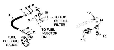
Remove nut (Figure 4-63, 1), ferrule (2), hose end (3), hose (4), nut (5), ferrule (6), hose end (7), and
elbow (8).
Figure 4-63. Fuel Lines from Fuel Pressure Gauge and Pressure Switch
(11)
Disconnect fuel injector line from elbow (9).
(12)
Remove elbow (9), tee (10), and elbow (11).
(13)
Remove elbow (12), pressure switch (13), tee (14) and pipe nipple (15).
b.
Repair.
(1)
Manufacture hoses per appendix F and RPSTL.
(a)
Cut material to the required length.
(b)
Insure the ends are flat.
(2)
Manufacture tubing per appendix F and RPSTL.
(a)
Cut material to the required length.
(b)
Insure the vent tube ends are flat and free of metal shavings.
c.
Installation.
(1)
Wrap antiseize tape (item 1, section II, appendix E) on threaded ends of elbows (Figure 4-63, 11), (12),
(13), (15), (9), and (8).
(2)
Install pipe nipple (15), tee (14), pressure switch (13) and elbow (12).
4-155

