• Home
  • Download PDF
  • Order CD-ROM
  • Order in Print
Figure 5-3. Coupling disassembly and reassembly.
Figure 5-5. Engine removal and instalaltion

TM-5-4310-270-15 Compressor Rotary Power Driven Air Two Impeller Wheel Barrow Frame Mounted Two Pneumatic Tires. Gasoline Engine 60 CFM 6.5 P.S.I. Manual
Page Navigation
  37    38    39    40    41  42  43    44    45    46    47  
Figure 5-4. Coupling removal and installation.
(4) Position engine and partly secure
b. Installation.
hardware.
(1) Install 5/8 bushing and half coupling
(5) Align coupling, figure 5-3, allowing
to compressor shaft.
no more than 2 degree misalignment.
(2) Install 3/4 bushing and half coupling
(6) Secure engine.
to engine shaft.
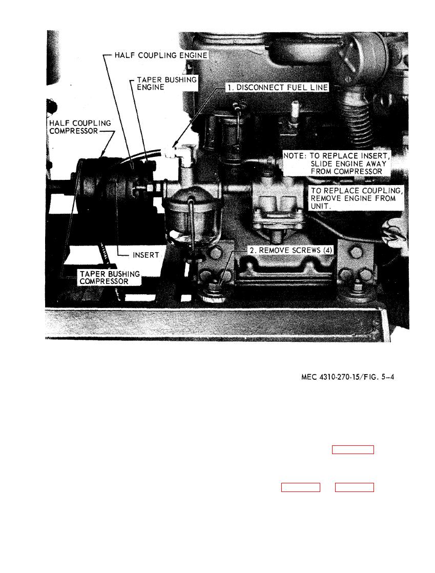
(7) Assemble components as illustrated
(3) Install rubber insert on air compres-
in figure 5-4 and figure 5-5.
sor side.
5-5


Western Governors University

Privacy Statement
Press Release
Contact

© Copyright Integrated Publishing, Inc.. All Rights Reserved. Design by Strategico.