
TM 5-4310-354-14
TS5-4310-354-14/7-15 (2)
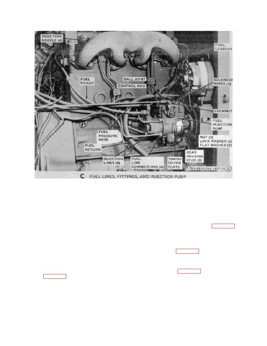
Figure 7-15. Fuel injection pump, removal and installation (Sheet 2 of 3).
(4) Check that number 1 cylinder is at 20 before
(5) Disconnect the fuel pickup hose, fuel pressure
top dead center. Determine this as follows:
hose, fuel return hose, fuel line leak off line, and
the four fuel injection lines from the pump.
(a) Remove injection nozzle from number 1
Reinstall the fuel connection screws and
cylinder. Place thumb over the nozzle
washers to prevent dirt from entering pump.
opening and feel for air being forced out
Remove all other fuel line fittings and plug the
during the compression stroke as the
fitting openings in the pump (figure 7-15).
engine is cranked.
(6) Remove lock nut from control rod swivel ball
(b) Check the timing mark on the flywheel in
joint and disconnect ball joint from pump lever.
relation to the timing mark on the fuel
Disconnect all wires from pump solenoid
injection pump. With fuel injection pump
terminals (figure 7-15).
timing marks aligned exactly, the exact
injection timing is indicated by the degree
(7) Remove cap screws, lock washers, thrust plate,
mark on the flywheel aligned with the
gasket, nut, lock washer, and injection pump
timing pointer. This degree should be 20
drive gear (figure 7-15).
7-17

