
TM 5-4310-370-14
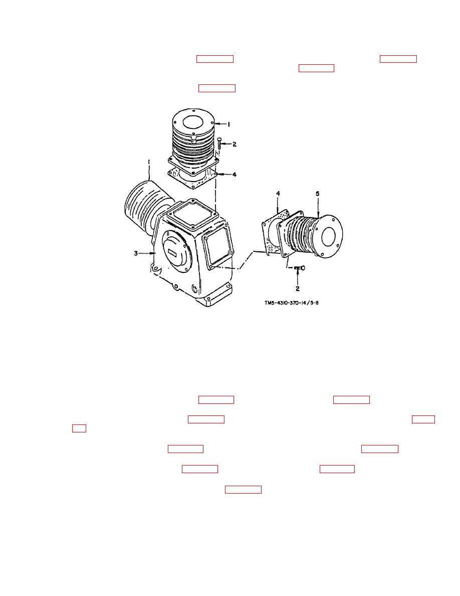
(a) Remove each low pressure cylinder (figure 5-8, item 1) by turning the four hex cap screws (figure 5-8, item
2) counter clockwise and then lifting off the cylinder from crankcase (figure 5-8, item 3).
(b) Remove both cylinder flange gaskets (figure 5-8, item 4).
TM 5-4310-370-14/5-8
1. Low pressure cylinders (2)
4.
Cylinder flange gaskets (3)
2. Hex cap screws (12)
5.
High pressure cylinder
3. Crankcase
FIGURE 5-8. CYLINDER REMOVAL AND REPLACEMENT
b. Piston and Rod Assemblies
(1) Remove six piston pin retaining rings (figure 5-9, item 1) and three piston pins (figure 5-9, item 2).
(2) Lift out both low pressure pistons (figure 5-9, item 3) and remove both low pressure piston ring sets (figure
(3) Lift out high pressure piston (figure 5-9, item 5) and remove high pressure piston rings (fi gure 5-9, item 6).
(4) Drain oil by removing oil fill plug (figure 5-9, item 7) and then oil drain cap (figure 5-9, item 8).
(5) When oil has drained, remove oil drain nipple (figure 5-9, item 9).
5-20

