TM 5-4310-370-14
TM 5-4310-370-14/5-10
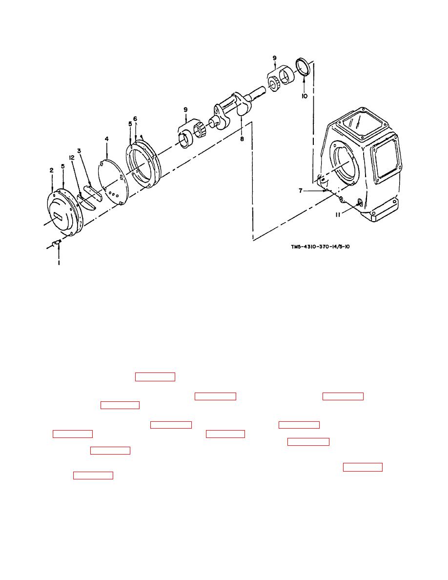
1.
Hex cap screws (4)
7.
Crankcase
2.
Breather chamber
8.
Crankshaft
3.
Breather element
9.
Main bearing cup assemblies (2)
4.
Crankcase cover
10.
Oil seal
5.
Crankcase cover gasket
11.
Visible sight oil gage
6.
Crankcase cover shims
12.
Oil separator
FIGURE 5-10. CRANKCASE ASSEMBLY
5-7. CRANKCASE REASSEMBLY.
a. Replace oil seal if it leaks (figure 5-10, item 11).
b. Replace both main bearing cup assemblies (figure 5-10, item 10) on to crankshaft (figure 5-10, item 9) and place
into crankcase (figure 5-10, item 8).
c. Reassemble crankcase cover (figure 5-10, item 4), breather element (figure 5-10, item 3), and breather chamber
(figure 5-10, item 2) using two hex cap screws (figure 5-10, item 1), one at the bottom and one at the top, leaving
out the cover gasket and shims at this time. Be sure main bearings (figure 5-10, item 10) on the end of the
crankshaft (figure 5-10, item 9) fit properly in cover. Set the two attaching hex cap screws finger tight. Using a
feeler gage, measure the gap between the cover and crankcase at top and bottom of cover. Average the two
dimensions and add 0.005 inch (0.0127 cm). This will determine the selection of gasket (figure 5-10, item 5) and
shims (figure 5-10, items 6 & 7) to use. A combination of these should equal
5-23


