
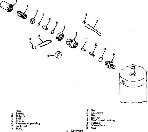
Figure 7. Water separator relief valve, exploded view
(8)and apply a torque to the fitting of 25 pound-
(8) Assemble the nameplate (15) after proper
feet.
stamping of the part number and pressure
(4)
Position the preformed packing (6) into the
setting.
body (8).
(9) Perform the test and calibration as indicated in f
(5)
Screw the locknut (7) onto the body (8).
below.
(6)
Wipe oil (OE30) on the inside diameter of the
(10)Secure the cap (1) and body (8) together using'
body (8) and then insert the piston (5) into the
the lockwire (17) and tag (16).
Secure the
body.
body, fitting (14) and locknut (7) together using
(7)
Hold the cap (1), with the opening up, and drop
the seal (9) and lockwire (10).
the spring (2), spring retainer (3) into the cap.
(11)Recheck the full flow and reseat pressure after
Center the ball (4) in the spring retainer.
lockwiring to make certain that the setting
Assemble the body and the cap.
adjustment has not been changed.
AGO 5548A
14