
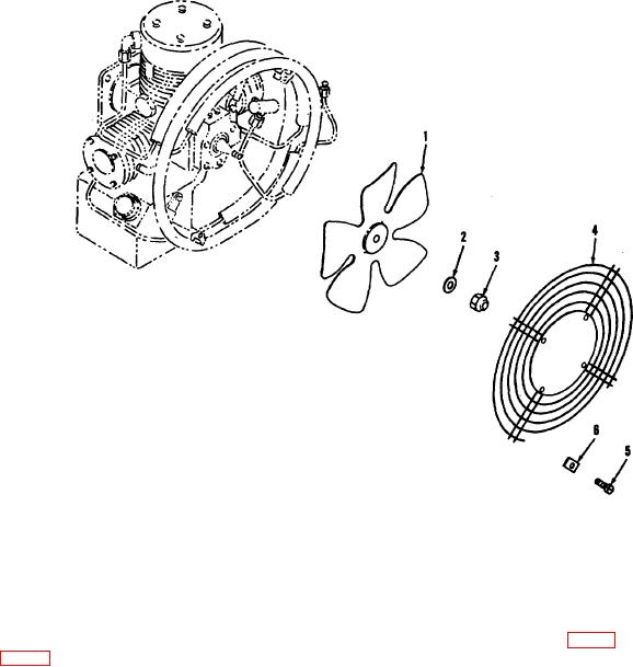
1
Fan
4
Fan guard
2
Washer
5
Screw
3
Nut
6
Washer
Figure 8. Fan and fan guard, exploded view.
(2) Position the fan guard (4) on the brackets (I and
with the screws (5, fig. 8), washers (6).
9, fig. 9) and secure
Section IV. INTERCOOLER AND AFTERCOOLER SECTION
around the fan and serve to cool the compressed air
26. Description and Function
passing from one stage to another. The moisture in the
The intercooler and aftercooler section consists of the
compressed air is both squeezed out and condensed by
first stage intercooler, second stage intercooler,
cooling. The entrained moisture is separated from the
aftercooler, fan guard brackets, cooler clamps, and the
compressed air by the water separator.
hardware required to secure the components.
The
intercoolers and aftercoolers are made of corrosion
27. Maintenance
resistant steel tubing with tin coated, low carbon steel
fins soldered to the tubing.
The end fittings of the
Fourth echelon maintenance personnel are authorized to
coolers consist of sleeves and nuts positioned at the
replace the first stage intercooler, second stage
flared ends of the tubing.
The intercoolers and
intercooler, aftercooler, fan guard brackets, and
aftercooler are positioned
attaching hardware.
AGO 5548A
16