Section IV. ENGINE GROUP
15. Description and Function
elbow, union, exhaust pipe, and the attaching hardware.
The engine group is a one cylinder, four-stroke, internal
a. Disassembly (fig. 5).
combustion, gasoline engine used to drive the air
(1) Disconnect and remove the tube assembly (10)
compressor group. A fuel tank, is attached to the frame.
from the connector and filter (11) and the
The gasoline flows from the tank through a connector
shutoff cock (7) after removing the nut (13),
and filter to a shutoff cock located at the glass filter bowl.
washer (14), screw (8), and tube clamp (9).
From the shut-off cock, the gasoline flows through the
(2) Unscrew the connector and filter (11) from the
filter bowl to the fuel metering system in the gasoline
fuel tank.
engine.
(3) Remove the preformed packing (12) from the
connector and filter (11).
16. Maintenance
(4) Unscrew the elbow (6) and shutoff cock (7)
Third echelon maintenance personnel are authorized to
from the filter bowl; unscrew the elbow from the
replace the fuel tank, preformed packings, connector and
shutoff cock.
filter, shutoff cock,
(5) Unscrew the filter bowl from the union (5).
(6) Unscrew the union (5) from the gasoline
engine.
(7) Disassemble the nut (4), washer (3), and screw
(1) and remove the exhaust pipe (2) from the
gasoline engine.
b. Cleaning and Inspection (fig. 5).
(1) Clean all metallic parts with dry-cleaning
solvent.
(2) Air dry and clean the connector and filter (11)
with compressed air.
(3) Inspect all components for damaged threads,
cracks, distortion or other defects.
(4) Replace preformed packing (12).
c. Lubrication.
(1) Apply antiseize compound per JAN-A-669 to all
threaded fittings.
(2) Apply oil per MIL-L-2104, OE-30 to preformed
packings.
d. Assembly (fig. 5).
(1) Position the exhaust pipe (2) on the exhaust
port of the gasoline engine and secure with the
screw (1), washer (3), and nut (4).
(2) Screw the union (5) into the carburetor inlet port
of the gasoline engine.
(3) Assemble the filter bowl of the gasoline engine
onto the union (5).
(4) Assemble the elbow (6) of the shutoff cock (7).
(5) Screw the elbow (6) to the inlet port of the filter
bowl.
(6) Position the preformed packing (12) on the
connector and filter (11).
(7) Screw the connector and filter (11)
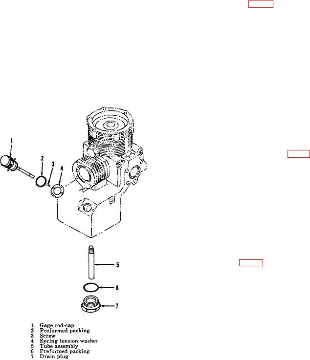
Figure 4. Oil sump accessories, exploded view.
AGO 668A
9

