
CHAPTER 2
DIRECT SUPPORT MAINTENANCE INSTRUCTIONS
Section I. MOISTURE SEPARATOR GROUP
2-1.
Description
2-2. Function
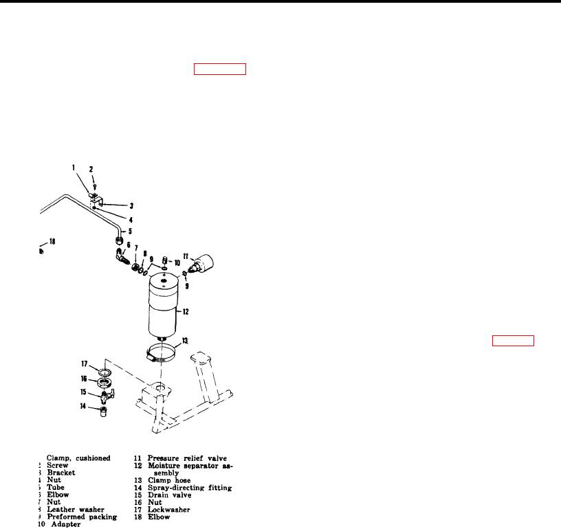
The moisture separator group (fig. 2-1) is
The moisture separator group serves to sep
located on the frame of the compressor and 3 held in
arate moisture and impurities from the high-pressure
place by a clamp (13). The moisture separator group
compressed air.
These impurities are removed
consists of a tube assembly (5), elbows (6 and 18),
periodically by opening the drain valve mounted on the
adapter (10), pray-directing fitting (14), drain valve (15),
base of the moisture separator assembly, thus allowing
pressure relief valve (11), and a moisture separator
high-pressure air to blow the accumulated moisture and
assembly (12).
oil condensate to atmosphere through the spray-directing
fittings. The pressure relief valve mounted in the
moisture separator assembly opens automatically to
exhaust high-pressure to atmosphere before pressure in
the shell reaches 2, 250 pounds per square inch. The
relief valve reseals, or closes, preventing the further
escape of air when pressure within the shell drops to 1,
950 pounds per square inch.
2-3.
Maintenance
Direct support maintenance personnel are
authorized to replace the clamp, backup washer,
adapter, drain valve, pressure relief valve, moisture
separator assembly, and hardware as required.
a.
Removal.
(1) Open drain valve (15, fig. 2-1) and
drain the moisture separator assembly.
(2) Remove screw (2) and nut (4)
attaching clamp (1) to bracket (3).
Remove tube assembly (5) from
between after cooler and moisture
separator. Remove bracket (3).
(3) Remove elbows (6 and 18). Remove
nut (7), washer (8), and packing (9).
Unscrew and remove adapter (10) and
packing (9). Remove pressure relief
valve assembly (11) and packing (9).
(4) Unscrew and remove fitting (14) from
drain valve (15). Remove drain valve.
Figure 2-1. Moisture separator group, exploded view.
Unscrew and remove nut (16) and
lockwasher (17).
6