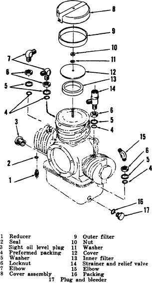
Lubrication.
c.
(1) Lubricate preformed packing with a
light film of pneumatic system
lubricating grease (MIIL-4343) during
assembly.
(2) Lubricate all male threads with
pneumatic system lubricating grease
(MILIL-4343) during assembly.
d.
Assembly.
(1) Install preformed packing (4), backup
washer (5), locknut (6), and elbow (7)
on first stage.
(2) Position inner cleaner (13) and cover
(12) on first stage cylinder and secure
with lockwasher (11) and nut (10).
(3) Install outer filter (9) and cover
assembly (8) on end of first stage
cylinder. Turn cover to lock cover slots
over pins on cylinder head.
(4) Install preformed packing (4), backup
washer (5), locknut (6), and elbow (15)
on second stage.
(5) Install
seal (2) and reducer (1) on third stage.
(6) Install preformed packing (4), backup
washer (5), locknut (6), and strainer
and relief valve (14) on second stage.
(7) Install preformed packing (4), backup
washer (5), locknut (6), and elbow (7)
on third stage.
(8) Place packing (16) over plug and
bleeder (17) and screw into port on the
oil reservoir.
Figure 2-3. Compressor assembly, partial exploded
(9) Install sight oil level plug (3) in
view.
Section IV. ENGINE GROUP
connector and filter, which filters the fuel on its way to the
2-8.
Description and Function
glass filter bowl. Gasoline then flows through the filter
bowl to the fuel metering system in the gasoline engine.
The engine is a single-cylinder four-stroke cycle
internal combustion overhead valve air-cooled engine.
2-9.
Maintenance
The engine is used to drive the air compressor. Included
with the gasoline engine are various accessory
components required to facilitate operation of the unit.
Direct support maintenance personnel are
The fuel tank, which is attached to the frame assembly,
authorized to replace the preformed packings, connector
stores the gasoline. The gasoline flows through the
and filter, clamp, elbow, nipple, and attaching hardware.
10

