
TM 3-1040-263-34
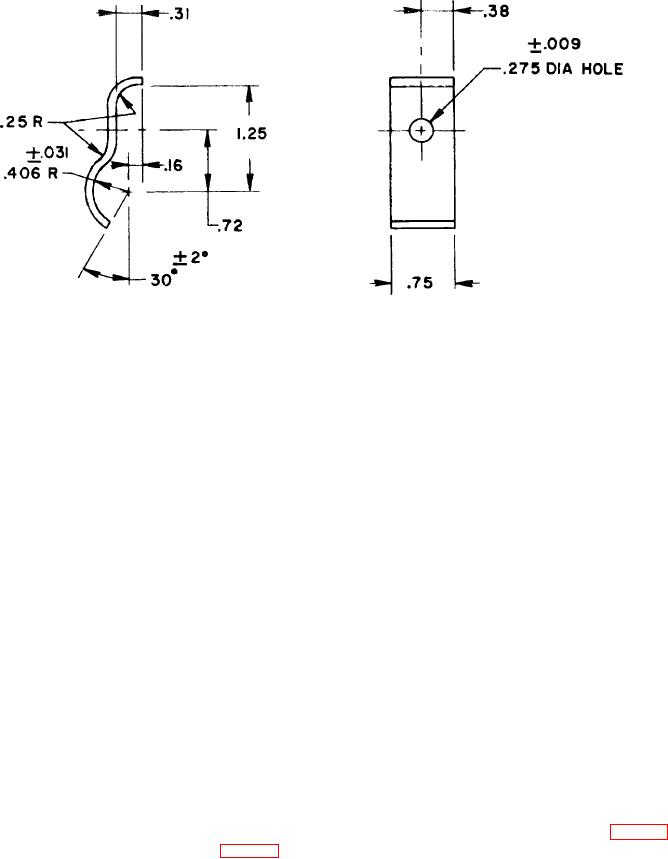
NOTES:
I. MATERIAL: ALUMINUM ALLOY 6061 SHEET TEMPER T6 0.090 INCH
NOMINAL STOCK THICKNESS SPECIFICATION QQ-A-250/11I
2. BREAK SHARP EDGES 0.010 INCH MAX.
,
3. SURFACE TREATMENT FINISH NO. 7.3.2 FOLLOW WITH SEMIGLOSS
PAINT SYSTEM NO. 21.5, COLOR OLIVE DRAB NO.X24087, MIL-STD-17.1
MU-E-312-34-4-20
Figure 4-20. Fuel tank clamp fabrication.
Section XI. GAS PLATE, COMPRESSOR NAMEPLATE,
PROTECTING CAGE, AND ENGINE MOUNTING FRAME
(3) Remove the backing from the new gas
4-59.
General
plate (27).
(4) Mount gas plate (27) by applying hand
General support maintenance personnel are authorized
pressure to the top of the plate.
to replace the gas plate, nameplate, mounts. and
attaching hardware.
4-61.
Compressor Nameplate
4-60.
Gas Plate (Fuel Tank)
a
Description.
The
aluminum-alloy
compressor nameplate identifies the unit.
The
a. Description. The fuel tank gas plate is
compressor nameplate is mounted to the bottom frame
made of aluminum foil and identifies the kind of fuel to be
by four rivets.
placed in the fuel tank. The plate is mounted by
pressure sensitive adhesive.
b.
Removal.
b.
Removal arid Installation
(1) Remove four rivets (32, fig. 3-2).
(1) Lift the edge of the gas plate (27, fig. 3-2)
(2) Remove nameplate (33).
with a sharp tool. Then, pull the plate completely off the
fuel tank (31).
c.
Installation.
(2) Clean the plate mounting surface with
(1) Position nameplate (33) to bottom
drycleaning solvent and air dry.
frame (38). Aline holes.
4-36