GOVERNOR
The K141 engine is equipped with governors and
operating speed is determined by throttle control setting.
The governor maintains engine speed tinder varying
loads and serves as a top speed limiting device.
Engines on some applications such as electric plants
hive constant speed settings.
Figure 6
Throttle Wire Actual Size
VARIABLE SPEED APPLICATION
OR THROTTLE CONTROL
Installation and Adjustment:
a. Bend end of throttle wire as shown in Figure 6.
b. With control handle in an open position, insert
throttle wire into speed control disc hole nearest
throttle bracket. (Fig. 7).
c. Install cable clamp and bolt to throttle bracket.
d. Remove drive pin (A Fig. 5) from speed control
disc (D Fig. 5) and operate control handle,
rotating disc from idle to full speed. See further
instructions below.
e. Operating speed range can be changed by
moving throttle as shown in Figure 8.
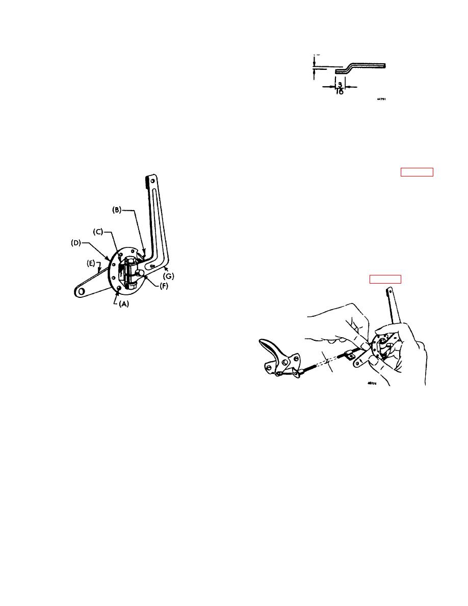
Figure 5
A - Drive Pin
D - Speed Control Disc
B - Governor Spring
E - Throttle Bracket
C - Bushing Nut
F - Governor Shaft
G - Governor Arm
Figure 7
Inserting Throttle Wire
GOVERNOR ADJUSTMENT
Governors are set when the engines wire assembled
and should not require readjustment unless governor
arm is loosened or removed from governor shaft.
a. To reset governor (Fig. 9) loosen nut which
holds governor arm ( I ) to shaft (H).
b. Turn shaft counter clockwise as far as possible
with a pair of pliers.
c. Pull arm ( I ) all the way to the left (away from
carburetor). Tighten nut. Check for freedom of
movement.
69


