Note:
The first or "SP" or "S" mark will
;appear 20 before top dead
center. The second mark is top
dead center and is stamped with
"DC" or "T" below the mark.
Figure 11
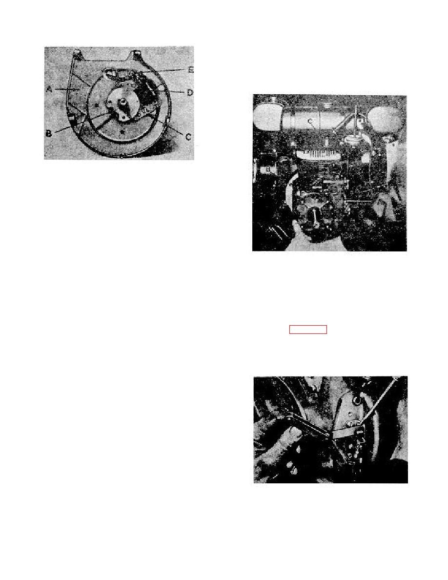
Phelon Magneto
A - Bearing Plate
C - Pole Shore
B - Magneto Rotor
D - Magneto Coil
E - Condenser
b. If there is no spark, check breaker points.
c. To test magneto, use a good commercial tester.
Refer to tester manufacturer's instructions for
Figure 12
acceptance limit of coils.
Setting Breaker Points with Timing Light
4. Testing Condenser
A - Breaker Points
B - Timing Sight Hole
C - Timing Light Attached to Spark Plug
Check condenser with reliable commercial con-
denser tester.
c. On earlier engines without timing sight hole,
point gap should be set at .020 when fully
5. Magneto
opened. Figure 13.
a. The K141 engine is equipped with the Phelon
d. Point clearance should be approximately .020
magneto as shown in figure 11.
fully opened. Clearance may vary a few
thousandths to achieve exact timing. This
b. The rotating magnet in both cases is mounted
variation is permissible.
directly on the crankshaft. Clearance between
the rotating magnet and pole shoes should be
about .002-.005.
c. Rotating magnet and flywheel are positioned on
the crankshaft with a single 1/4"square key.
6. Ignition Timing
a. Current production engines are equipped with a
timing sight hole in left side of bearing plate,
when viewed from power-take-off side of
engine.
b. If a timing light is available, set breaker point
Figure 13
gap while engine is running between 1200 and
Adjusting Points
1800 RPM. Adjust until "SP" or first mark on
flywheel is centered in sight hole. See figure
12.
71


