8. Attaching Rod to Crankshaft
b. It is important that a new gasket be used to
prevent oil leakage.
a. After Piston Assembly is installed, place block
on end and oil connecting rod and crank pin.
c. Use 3/16" pilot studs to align cylinder block,
gasket and oil base.
b. It is important that marks on connecting rod and
cap (A, Fig. 24) line up and face flywheel end
of engine. (B, Fig. 24) c. Connecting rod cap,
lock and cap screws ;ire then attached to
connecting rod.
d. Use a torque wrench to tighten cap screws to
220 inch pounds. Back off screws and tighten to
200 inch pounds. This two-step procedure will
assure a tight fit of rod to crankshaft and avoids
possibility of screws tightening in threads while
rod remains loose on shaft.
Figure 27
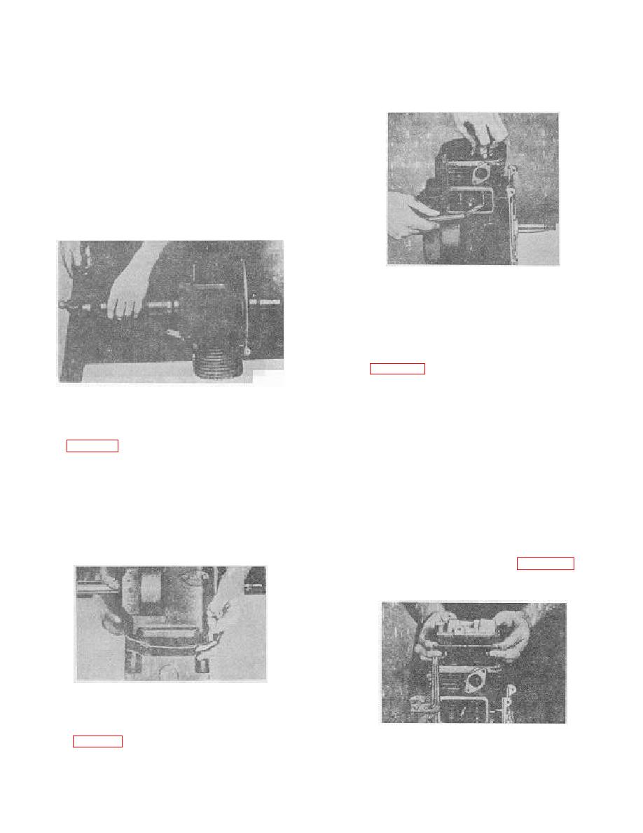
Checking Valve Clearance
11. Installing and Setting Valves
a. Valves, valve seats and ports should be
thoroughly cleaned. Valves should be ground
and lapped-in to obtain a good valve seat.
Keep valve seat from 1/32"to 1/16" in width.
b. Figure 27 illustrates checking valve clearance.
Intake valve clearance should be .006/.008 cold.
Exhaust valve clearance should be .015/.017
Figure 25
cold. Valves that do not have the correct
Installing Oil Seals
clearance must be removed and ends ground
until desired clearance is obtained. ENDS
9. Installation of Oil Seals on Crankshaft
MUST BE GROUND SQUARE AND ALL
a. Figure 25 shows two oil seals on crankshaft.
BURRS MUST BE REMOVED.
b. Guide oil seals into position on crankshaft
c. After correct clearance is obtained, remove
without damaging lips of seals. Any foreign
valves and install valve springs and retainers
matter on knife-like edge or any bending of seal
and rotors. Replace valves, compress springs
may cause damage and an oil leak can result.
and place locking key in grooves of valve
c. After oil seals are started on shaft, place block
stems.
on its side. The oil seals may now be driven
12. Cylinder Head
squarely into bearing plate and cylinder block.
a. Always use a new gasket when head has been
removed for service work. Figure 28. Head
gasket should be soaked in water before
assembly.
Figure 26
Installing Oil Base
10. Oil Base
a. Assemble oil base to block with four screws.
Figure 28
Cylinder Head Assembly
76


