TM 5-4310-227-15
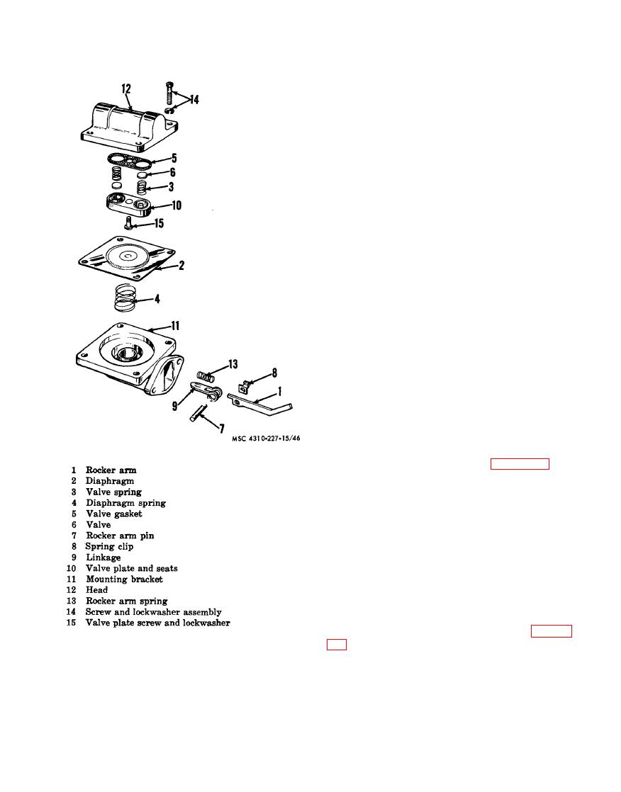
(5) Hold the mounting bracket (11) in
the left hand, with the rocker arm
(1) toward the body, and the thumb
nail on the end of the linkage (9).
With the heel of the right hand on
t h e diaphragm (2), compress dia-
phragm spring (4) and at the same
time turn the diaphragm clockwise
90. This will unhook the diaphragm
from linkage (9). Discard spring (4)
and diaphragm (2).
c. Cleaning, Inspection, and Repair.
(1) Clean all parts with an approved
cleaning solvent and dry thoroughly.
(2) Inspect all parts for breaks, cracks,
and signs of wear.
(3) Replace all defective parts.
d. Reassembly.
(1) I n s t a l l - the new valve spring (3) and
valve (6) in their proper position in
the head (12). Install a new gasket
(5) and the valve plate and seats (10)
and secure with screw (15).
(2) Install a new spring (4) in the mount-
ing bracket (11 ).
(3) Install the new diaphragm (2), re-
v e r s i n g the procecdure in ( b ( 5 )
above).
(4) Install rocker arm spring (13).
(5) Install the partially assembled fuel
pump on the engine (para 3-41).
(6) Slowly crank the engine until the di-
a p h r a g m (2) is laying flat on the
Place the
mounting bracket (11).
head (12) in its proper position on
the mounting bracket (11) and install
the screw and lockwasher assemblies
(14) approximately three turns.
(7) Slowly crank the engine until the di-
a p h r a g m (2) is pulled down into
mounting bracket (11) and tighten
the screw and lockwasher assemblies
(14).
Section Vlll.
ENGINE PISTON AND CONNECTING ROD ASSEMBLY
a scraper ring, and an oil control ring. The pis-
4-30. General
ton pin is of hollow steel and is held in place
The piston is an aluminum alloy, four-ring
with a retailing ring at each end. The connect-
piston. The piston has two compression rings,
ing rod is fitted with a sleeve bearing for the


