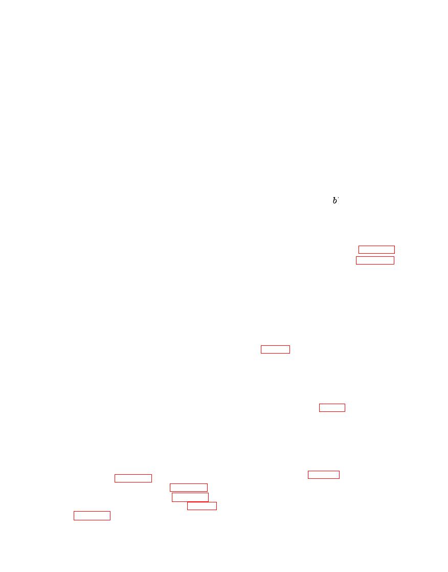
TM 5-4310-227-15
Caution: Do not turn the crank-
place the entire connecting rod as-
shaft while the plastic gage is be-
sembly if the proper clearance can-
ing used.
not be obtained.
Note. Do not discard the two shims.
(c) Remove the two nuts and pull off
In the event connecting rod assembly
the rod cap.
Then compare the
replacement is necessary, the shims may
width of the flattened plastic gage,
be needed to obtain the correct fit of
at its widest point, with gradua-
the new assembly on the crankshaft.
tions available on the envelope-
(10) After the correct clearance is obtain-
type container for the plastic gage.
ed, remove all traces of plastic gage
The number within the graduation
material from the bearing surfaces
on the container indicates the
a n d the crankshaft journal. Again
bearing clearance. The clearance
c o a t the bearing surfaces and the
should be 0.0007 to 0.0002 inch.
crankshaft journal with a light film
(d) If the clearance indicated is greater
of clean lubricating oil and install the
than the required dimensions, re-
shims, if needed, and the rod cap as
peat the measuring operation de-
instructed in (9) ( ) above.
scribed in a through c above, with-
(11) Install the 2 stamped nuts (18) that
out using the two shims (29) under
lock the 2 hex nuts (17) in position.
the rod cap (16).
Then rotate the crankshaft to be sure
(e) If a slight amount of clearance is
it turns freely.
still indicated, the rod cap may be
(12) Install the cylinder head (para 3-70).
filed lightly on the mounting sur-
(13) Install the engine base (para 4-27).
faces to obtain the proper fit. Re-
Section IX. ENGINE CRANKSHAFT, CAMSHAFT,
VALVE LIFTERS, AND GOVERNOR
secure the drive pulley end plate (20)
4-32. General
to the cylinder and crankcase assem-
The crankshaft is made of forged steel and
bly (19) and remove the plate and
is supported at each end by a tapered cone and
four end plate gaskets (22 and 23,
rollers. The camshaft is driven by a helical
gear on the crankshaft and rotates on a sup-
shaft (15).
port pin through the center of the camshaft,
Note. The end plate gaskets are used
which is secured in the crankcase at both ends.
to obtain correct crankshaft end play.
Cam lobes on the camshaft actuate the valve
(5) Slowly rotate the crankshaft until the
lifters and oil pump. A flyweight-type cen-
counterweights are clear of the cam-
trifugal governor at the end of the camshaft,
shaft gear (14, fig. 4-8). Then care-
opposite the camshaft gear controls the engine
fully remove t h e crankshaft (2)
speed. Refer to TM 5-2805-203-14 for data
t h r o u g h the opening in the drive
applicable to model OEG-458-ENG-3.
pulley end of the cylinder and crank-
case assembly (7).
(6) Using a suitable puller, or an arbor
a. Removal and Disasembly.
press, carefully remove the cone and
(1) Remove the piston and connecting rod
roller (24, fig. 4-11) from each end
assembly (para 4-31).
of the crankshaft (15).
(2) Remove the air shroud (para 3-54).
(7) I n a similar manner, remove the
(3) Remove the drive pulley (para 3-66).
crankshaft gear (31 ) from the crank-
(4) Remove the four capscrews (22, fig.
shaft; then remove the woodruff key


