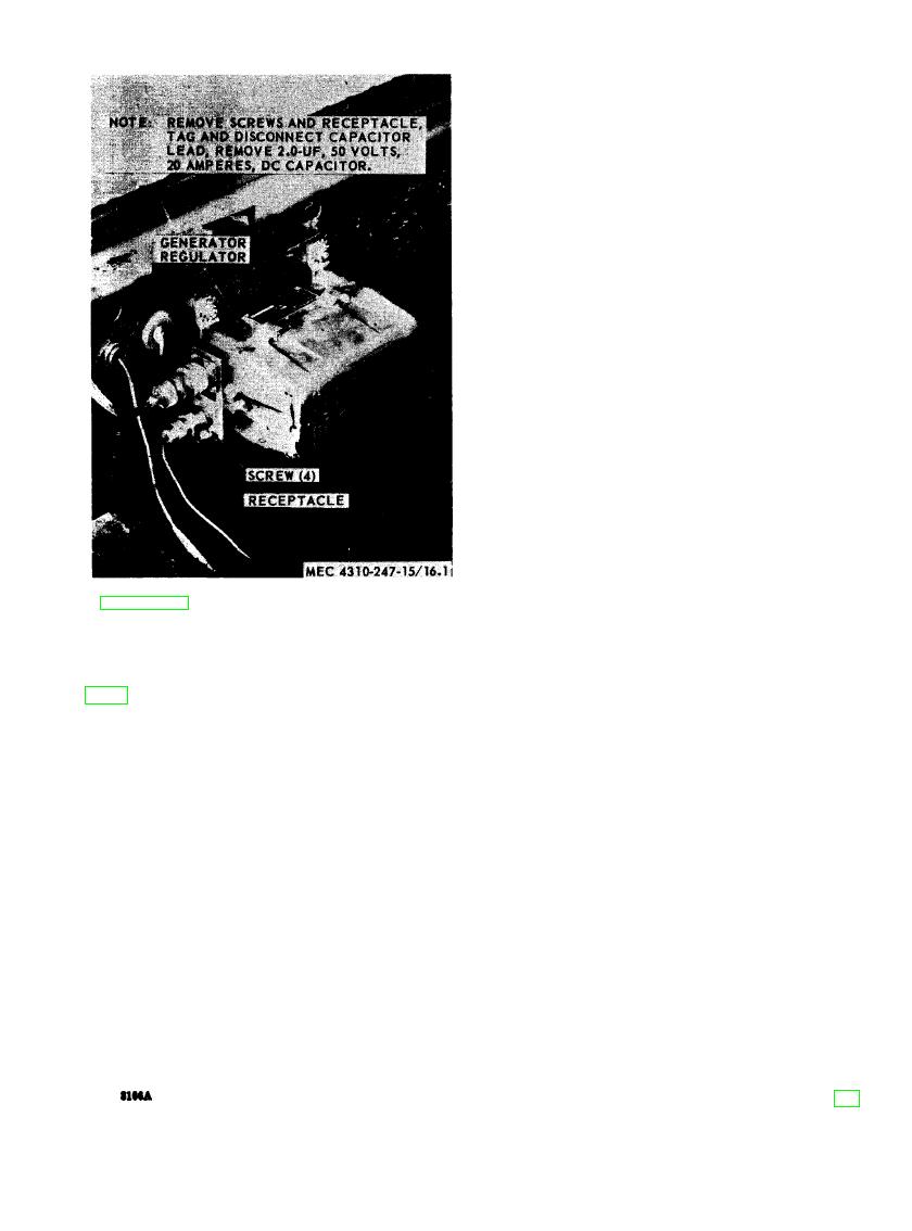
ence is indicated, isolate the cause of interfer-
ence by the trial-and-error method of replacing
each capacitor in turn until the cause of inter-
ference is located and eliminated.
removal and installation.
Section VII. BODY
(3) Paint all surfaces where the paint has
been removed or damaged. Refer to
a. Removal
TB 740-93-2 for detailed instruction.
(1) Remove the screws (26, fig. 17),
(4) Inspect the door holders, door catches,
washers (19) and nuts (23) that se-
and hardware for damage or wear and
cure the doors (27) to the housing
replace is damaged.
(32). Remove the dears.
(2) Remove the screws (26), washers
c. Installation.
(19), and nuts (23) that secure the
(1) Position the door holders (15) on the
front lower panel (28). Remove the
doors (27) and secure with screws
panel.
(14), washers (3) and nuts (1).
(3) Remove the screws (14), washers (3),
(2) Position the front lower panel (28)
and nuts (1). Remove door holders
on the housing (32) and secure with
(15).
screws (26), washers (19), and nuts
b. Cleaning and Inspection.
(23).
(1) Clean all parts with an approved
(3) Position the doors (27) on the housing
cleaning solvent and dry thoroughly.
(32) and secure with screws (26),
(2) Inspect for dents, breaks, cracks, rust,
washers (19) and nuts (23).
damaged hinges, or other damage. Re-
place parts if damaged.
AGO


