Home
Download PDF
Order CD-ROM
Order in Print
Adjustment.
Figure 5-3. Coupling disassembly and reassembly.
TM-5-4310-270-15 Compressor Rotary Power Driven Air Two Impeller Wheel Barrow Frame Mounted Two Pneumatic Tires. Gasoline Engine 60 CFM 6.5 P.S.I. Manual
Page Navigation
35
36
37
38
39
40
41
42
43
44
45
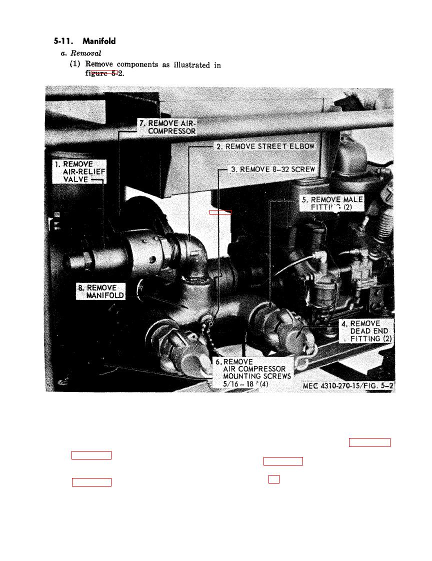
Figure
5-2.
Manifold
removal
and
installation.
b.
Installation
5-12.
Coupling
(1)
Install
manifold
on
compressor
.
a.
Removal
(2)
Position
compressor
on the mounting
(1)
Disconnect
ground
cable,
figure
3-5.
plate,
assemble
and
align
coupling,
(2)
Disconnect
components
as
illustrated
figure
5-3.
in
figure
5-4.
(3)
Secure
compressor.
(3)
Disassemble
coupling
as
shown
in
fig-
(4)
Install
components
as
illustrated
in
ure
5-3.
figure
5-2.
5-3