TM 5-4310-275-14
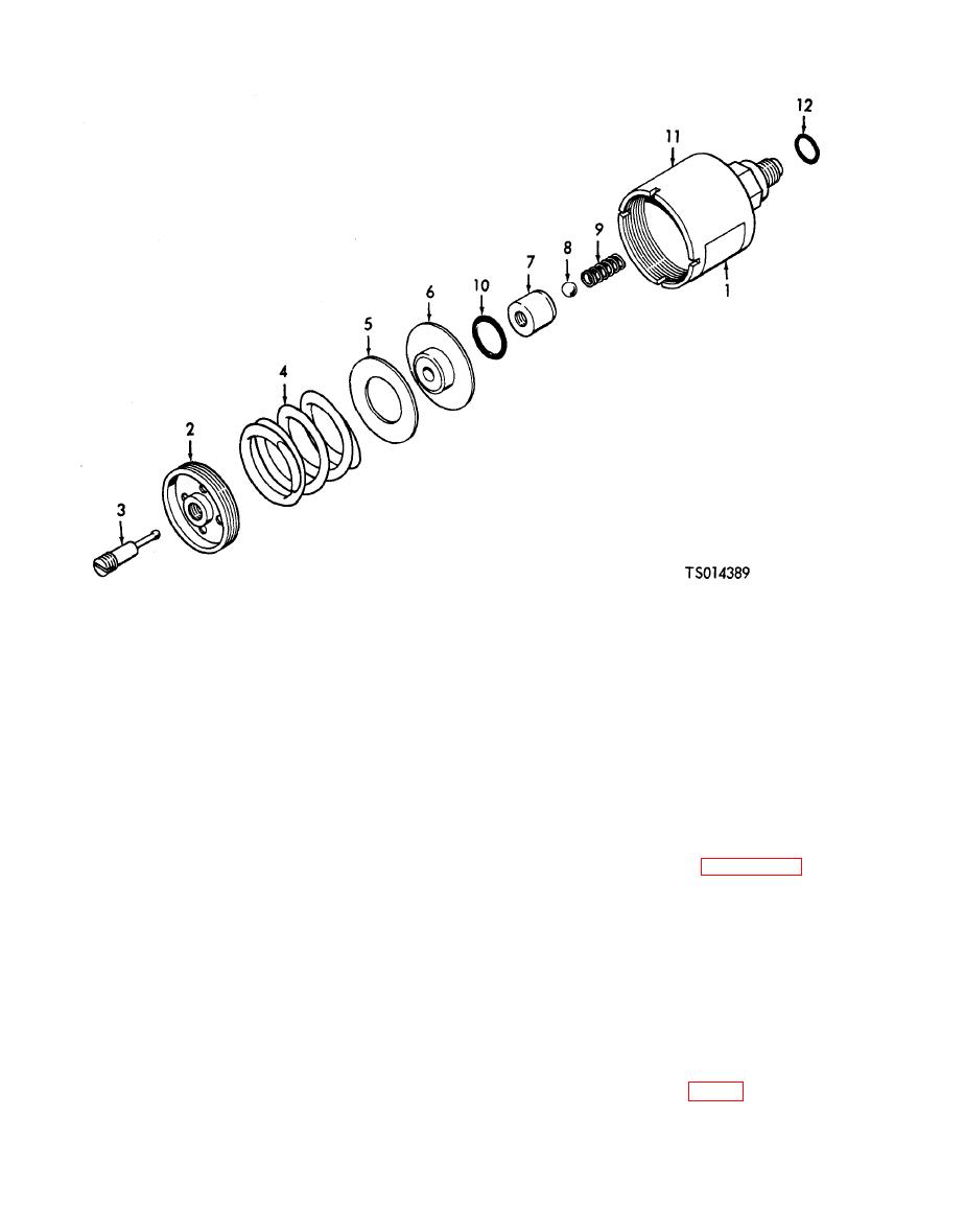
7.
Piston assembly
1. Identification plate
8.
Ball
2. Adjusting screw
9.
Spring
3. Stem
10.
Preformed packing
4. Spring
11.
Body
5. Spring shim
12.
Gasket
6. Spring retainer
adjusting screw and metal ball for scoring,
WARNING
scratches, nicks and signs of wear.
Dry cleaning solvent, Fed. Spec. P-D-680
(4) Do not attempt to repair damaged or
or P.S-661, used to clean parts is
questionable parts. Discard all such items and
potentially dangerous to personnel and
install new parts during reassembly.
property. Avoid repeated and prolonged
e. Reassembly. Refer to Figure 6-1 and
skin contact. Do not use near open flame
assemble the pressure relief valve.
or excessive heat. Flash point of solvent
(1) Apply a thin film of pneumatic system
is 100 F. (38 C.) --138 F. (59 C.).
grease (Specification MIL-G-4343) to new O-ring
d. Cleaning and Inspection.
packing (10), packing groove in body (11), and
(1) Wash all parts with dry cleaning solvent,
mating surfaces of body and piston assembly (7).
Fed. Spec. P-D-680, and dry -thoroughly with
(2) Insert O-ring packing (10) in groove in
clean, lint-free cloths. Use filtered, compressed
bore of body (11). Install ball return spring (9)
air to blow solvent. and residue from all crevices,
and metal ball (8) in bore of body.
springs, and air passages.
(3) Install piston assembly (7) in body (11)
(2) Inspect parts for damaged screw threads,
and down over metal ball (8) and spring (9).
cracks, breaks, or worn areas in anodized sur-
(4) Insert spring retainer (6), cupped side
faces, and other obvious indications of wear,
against piston assembly (7, fig. 6-1 ).
damage and deterioration,
(5) Place shims (5) and spring (4) in body
(3) Inspect finished surfaces of body, stem,


