TM 5-4310-275-14
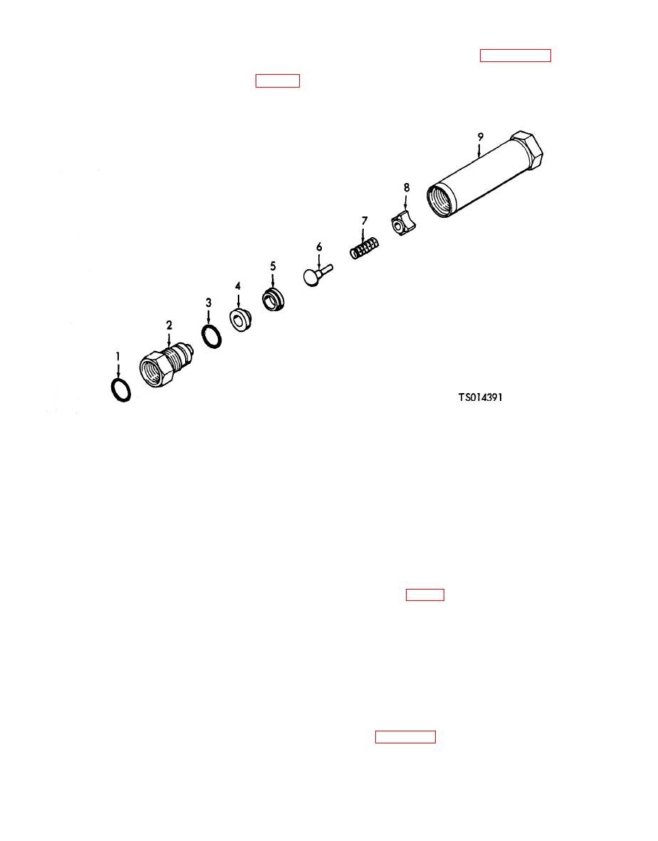
c. Disassembly. Refer to Figure 6-3 and
pneumatic system to prevent reverse air flow
disassemble the check valve in the sequence of the
from the pressure tank.
index numbers.
31).
6. Poppet
1. Gasket
7. Spring
2. Body screw
8. Poppet guide
3. Preformed packing
9. Valve body
4. Valve seat
5. Seat retainer
of spring should be 0.396 0.005 inch (1.0058
WARNING
.0127 cm).
Dry cleaning solvent, Fed. Spec. P-D-680
( 4 ) Discard all damaged, worn and
or P-S-661, used to clean parts is
questionable parts.
potentially dangerous to personnel and
e. Reassembly.
property. Avoid repeated and prolonged
(1) Apply a thin film of pneumatic system
skin contact. Do not use near open flame
grease, Specification MIL-G-4343, to threads of
or excessive heat. Flash point of solvent
body screw (2, fig. 6-3).
is 100 F. (38 C.) --138 F. (59 C.).
(2) Install poppet guide (8), spring (7),
d. Cleaning and Inspection.
(1) Wash all parts in dry cleaning solvent,
poppet (6), seat retainer (5) and valve seat (4) in
Fed. Spec. P-D-680. Do not soak parts. Dry
valve body (9).
thoroughly with clean, filtered, compressed air or
(3) Position O-ring packing (3) in groove of
body screw (2). Screw body screw into valve body
(2) Inspect parts for evidence of damage and
(9) and tighten with a torque of 600 25 pound-
wear such as stripped screw threads, scratches
inches (6.9702 .2904 kgm).
and scoring of finished surfaces, nicks and burrs
f. Test. Test the reassembled check valve as
on valve surfaces.
follows:
(3) Check poppet return spring for defor-
(1) Install the check valve in a test setup as
mation and damage. Spring must be cylindrical
shown in Figure 6-4.
in shape with ends closed and square. Free length


