5-9.5. The new crankshaft may be inserted into the crankcase from the crankcase end cover
side. Since the assembly is a moderate press fit, it may be forced into position by tapping it
with a lead hammer. (Be careful to strike the center of the shaft, since an off center blow
may spring it. )
5-9.6. The assembly must be driven in until the snap ring groove in the outer bearing clears
the end of the crankcase by about 1/16". Replace the snap ring by putting one end in the
groove and springing the ring into place.
5-9.7. Tap the crankshaft back until the snap ring is tight against the crankcase.
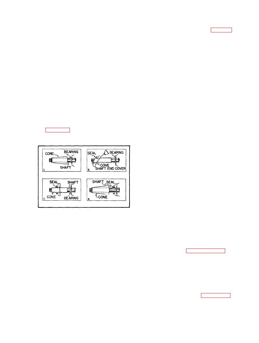
no burrs on the flywheel end of the crankshaft and that the edges of the keyway are smooth
and slightly rounded to prevent damage to the oil seal. When satisfied that the crankshaft is
smooth, replace the shaft end cover. As an added precaution against cutting the oil seal, an
assembly tool can easily be made in the form of a truncated cone of a .003" brass shim stock.
See Figure 5-9.
5-9.9. Re-assemble the rest of the com-
press or, using caution when replacing the
cylinders over the pistons. We recommend
the use of a piston ring compressor in this
operation.
5-9.10. Fill the crankcase with oil.
5-10. OIL SEAL REPLACEMENT. Re-
move the flywheel, key and shaft end cover.
The oil seal may be removed from the cover
by prying under the inside lip with a pinch
bar, or driving it out with a metal rod.
5-10.1. Insert the new seal with the seal-
ing lip facing in the same direction as the
one removed and coat the outside diameter
of the seal with shellac or pipe compound. Press the seal into the shaft end cover with a
vise or in a press. Note: Protect the parts from damage by serrated vise jaws by padding
the vise jaws.
5-10.2. After the seal has been installed in the shaft end cover, it is returned to its original
location by sliding it over the end of the crankshaft as described in Paragraph 5-9.8 of
Crankshaft Assembly Replacement.
5-11. PRESSURE SWITCH ADJUSTMENT. The pressure switch has a cut-out adjustment
and a differential adjustment. The cut-out is the pressure at which the switch contacts open,
and the differential is the span between the cut-in and cut-out settings. Note: There is inter-
action between these two adjustments; i. e., if the cut-out is increased, the differential will
also increase, or if the differential is narrowed, the cut-out will be reduced, etc. These
factors must be considered when adjusting the switch and compensated for accordingly. The
cut-out point may be increased by screwing the range nut clockwise. See Figure 5-10.
5-9


