SEPARATING THE PISTON FROM THE ROD. To separate the piston from the con-
5-8.
netting rod, proceed as follows:
5-8.1. Remove the air head cap screws (Figure 5-4) and pull the air head off the cylinder.
If the gasket sticks, remove it with a thin blade.
5-8.2. Disconnect any assemblies or piping that may prevent removing the cylinder. Now,
take out the cap screws securing the cylinder to the frame and pull the cylinder over the
piston.
5-8.3. To avoid bending the connecting rod when driving out the piston pin, we recommend
removing the piston and rod assembly from the crankshaft. To do this, drain the oil from
the frame and remove the frame end cover. Then, take the centrifugal unloader assembly off
the end of the crankshaft and pull the connecting rod off its throw.
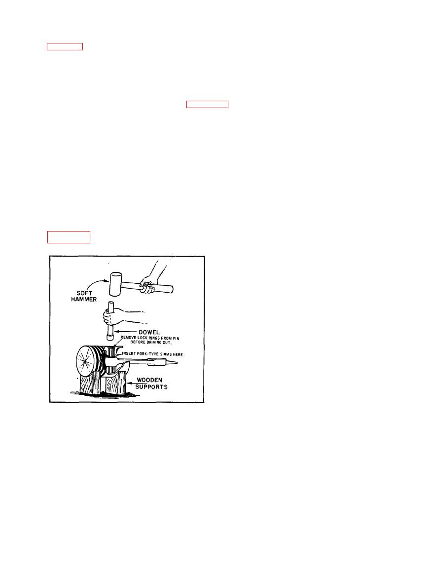
5-8.4. Remove the piston pin lock rings from their grooves and with a dowel of appropriate
size and a soft hammer, drive out the piston pin. Important: To prevent piston distortion
during this operation, play between the piston pin bosses and connecting rod must be elimi-
nated by inserting fork-type shims of the necessary thickness between the rod and boss. See
ASSEMBLY RE-
CRANKSHAFT
PLACEMENT. A new crankshaft assembly
includes bearings, spacer etc. , all of which
are installed as a unit. To remove the old
crankshaft and install a new one, refer to
Figure 6-2 and proceed as follows:
5-9.1. First remove the fan-type flywheel,
f l y w h e e l key and shaft end cover. Next,
d r a i n the crankcase oil, then remove the
c r a n k c a s e end cover and centrifugal un-
l o a d e r assembly.
5 - 9 . 2 . Remove the cylinder to crankcase
cap screws and pull the cylinders over the
pistons. Remove the centrifugal unloader
a n d connecting rods from the end of the
crankshaft, and take the snap ring from the
outer bearing. It may be necessary to drive
t h e c r a n k s h a f t e n d w i s e b e f o r e removing
Figure 5-8. Recommended Method of
snap ring.
Removing or Replacing Piston Pin
5-9.3. The crankshaft assembly is a moderate press fit in the crankcase and may be forced
out by tapping the flywheel end of the shaft with a lead hammer.
5-9.4. Prepare the new crankshaft assembly for installation by removing the snap ring from
the outer bearing, grasping it near the end and springing it from the groove.


