Fed. Spec. P-D-680 to remove oil and dust film. If the
(1) Visually inspect for excess accumulations
belts appear to have been saturated, and the heat has
of dust; dirt, or film of oil.
glazed the surfaces of the vee's, proceed as follows:
(2) Test for heat by touching intercooler tube,
(2) Use a medium grade of grit paper (not
aftercooler tube, or cylinder head.
emery cloth) and rough up the surfaces with strokes of ':
uneven direction.
(3) Check pilot valve for signs of leaking.
(3) wipe off all grit particles. When surface has
(4) Listen for excessive start-stop cycling.
been deglazed, install the belts on pulleys.
(5) Listen carefully for a knock or rattle that,
c. Adjustment.
might signify internal damage.
NOTE
(6) When any of these inspections disclose
When installing new belts, never
abnormal conditions, refer to Table 3-3 above.
pry the belts over the pulley groves.
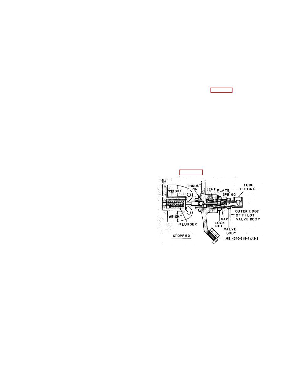
3-9. Pilot Valve
(1) Be sure that the motor has been moved'
a. General.
The pilot,-valve is a part of the
closer to the compressor, by loosening of mounting nuts,;
compressor -unloading system. As the compressor stops,
coupled with loosening of adjusting nut.
and the unloader weights retract, the plunger moves the
thrust pin outward which unseats the pilot valve plate and
(2) Place belts :(the matched pair) in: proper
allows pressure to bleed off cylinders through the pilot
grooves, then move motor away from compressor and
valve tube line and gaps between pilot valve body and its
tighten mounting nuts.,
boss. With out this unload in procedure, starting the
NOTE
compressor would likely cause the overload relay to trip,
A quick check for proper belt
and excessive wear on the belts and motor bearings. A
adjustment, is to observe belts
leaking, or maladjusted pilot valve will keep the
while compressor is-in operation.
compressor from unloading when stopped
If bottom of belt seems to droop
slightly below line from pulley to
b. Adjustment. To adjust. the outside exhaust pilot
valve, refer to figure 3-3 and proceed as follows:
pulley, the belts should be in
adjustment.
(3) A measured adjustment, assuring no strain
on bearings, is accomplished as -follows:
(a) Measure distance; between -pulley centers.
(b) At center -of belt span, .apply a force
perpendicular to the .span, by attaching a spring scale to
both belts. The force applied to the spring scale should
be sufficient to deflect the belts 1/64 in. for every inch of
span. If span is 36 in., the deflection should be 9/16 in,
and the scale should register 11/4 lbs. If scale registers
less than 1 7/8 lbs, the belt should be loosened slightly. If
scale registers less than 1 lbs, the belts would be
Figure 3-3. Adjusting the unloader pilot valve.
tightened slightly.
(1) Remove the tube fitting and withdraw the
NOTE
spring.
New drive belts may be left a little
tight, to take care of stretch during
(2) With a small rod, push the plate in against
the resistance of the thrust pin until the plate is firmly
run in.
seated. Make a mark on the small rod, on a line with the
3-8. Air Compressor
outer edge of pilot valve body. Now, permit the thrust pin
a. General.
The compressor unit part of the
to push the plate away from the seat as far as it will, and
assembly, kept clean and lubricated, should be relatively
mark this position, on the small rod.
free of maintenance. However, if the on-off cycles are
too frequent because of heavy use, and accumulations of
(3) The correct stroke, or measurement
dust and dirt cover the frame, intercooler, or aftercooler,
between the two marks on the small rod, is between
the compressor will run hot. Excessive heat consumes
0.0625 in. and 0.125 in. Should the measurement be
compressor oil. Low oil causes ring wear, or cylinder
under 0.0625 in., back off the locknut and turn -pilot valve
scoring. Therefore, frequent inspections are necessary.
body clockwise until measurement is at least 0.0625
b. Inspection.
3-6


