CHAPTER 4
ORGANIZATIONAL MAINTENANCE INSTRUCTIONS
Section I. SERVICE UPON RECEIPT OF MATERIEL
and general accessibility.
Position belt wheel side
4-1. Inspecting and Servicing the Equipment
towards a wall, leaving at least 15 inches for air
circulation to the belt wheel fan.
storage in a new or used condition. In either case, a i pre-
operative check must be made to assure that the
c. Installation. To prevent vibration and insure
equipment and its components are. ready for operation
proper operation, it is important that the unit be level and
without danger to equipment or personnel.
the receiver feet pulled down on shims in such a manner
as to avoid pre-stressing the feet and receiver. Install on
b. Inspecting the Equipment.
base as follows:
(1) Inspect the motor identification plate for
(1) Position feet over bolts, start nuts on bolts.
current and voltage specifications, and compare with the
electric service available. Check that the motor is
(2) Tighten. evenly any three of the nuts, to a
correctly wired. Be particular about checking the wiring
moderate torque, then check the unit for level. If not
and voltage of a dual voltage motor.
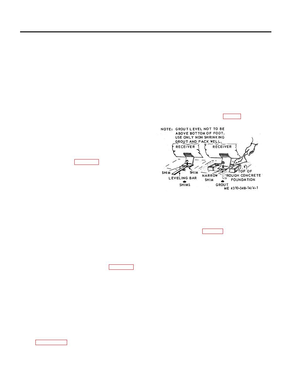
level, insert metal shims, or grout (fig. 4-1) under one or
two of the feet to obtain level, and re-tighten the nuts.
(2) Inspect the assembly for any obviously
missing parts, or damages that may have occurred during
transit.
(3) Check for all parts that may have been
removed and packaged separately for shipment.
(4) Inspect the
drive V-belts (a matched pair).
Check the adjustment
compressor drive wheel
through several revolutions by
hand. This will assure
that everything is free and in
working order.
c. Servicing the Equipment. Service the compressor
frame with compressor oil.
Figure 4-1. Leveling the air receiver.
NOTE
(3) Check the distance the unanchored foot is
The motor driving this compressor
elevated above the base, and insert metal shims under
has ball bearings lubricated for life.
this foot, sufficient to provide firm support.
It has no grease fittings, or plugs
(4) After all shims are inserted and the unit is
near the bearings, and requires no
level, tighten nuts on all feet to a moderate (not
lubrication.
excessively tight) torque (table 1-1).
4-2. Installation
d. Power. When the available power supply is equal
a. General The unit may be bolted to any relatively
to that required by motor (para 4-lb. above), and no other
level floor or base. If such a surface is not available, an
electrical equipment is on the circuit, number 8 AWG wire
adequate base must be constructed. Should a concrete
connected to a feeder not more than 100 feet away, will
base be necessary, be certain that bolts are imbedded
carry the load.
correctly to accept the feet of the receiver, and extend at
least one inch above the base. Refer to figure 1-3 for
mounting dimensions.
b. Location.
Choose a clean, relatively cool
location, if possible, and provide ample space for cooling
Section II. REPAIR PARTS, SPECIAL TOOLS, AND EQUIPMENT
4-3. Special Tools and Equipment
4-4. Maintenance Repair Parts
There are no special tools or: equipment required to
Repair parts and equipment are listed and illustrated in
perform maintenance on the air compressor.
the "Repair Parts and Special Tools List" TM 54310-348-
24P.
Section Ill. LUBRICATION INSTRUCTIONS
Refer to Paragraph 3-2 for lubrication instruction for this air compressor.
4-1


