TM 5-4310-356-14
Table 5-1. Troubleshooting (Cont'd)
MALFUNCTION
TEST OR INSPECTION
CORRECTIVE ACTION
adjustment is necessary shut off the outside power source.
b. Remove cover from pressure switch.
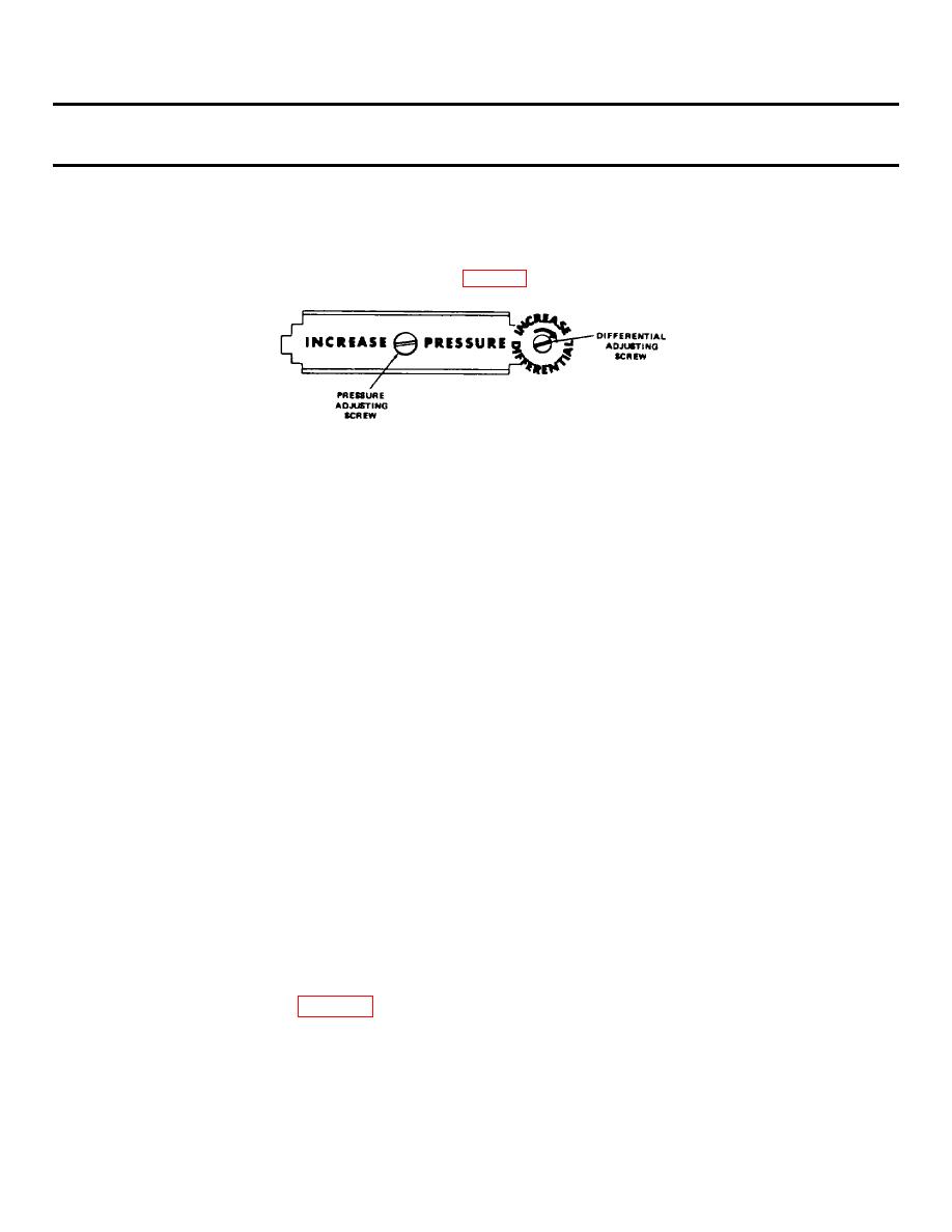
c. To raise the CUT-IN and CUT-OUT pressure turn the pressure adjusting screw
clockwise (fig. 6-5).
d. To decrease the difference between the CUT-IN and CUT-OUT pressure, turn the
differential screw counterclockwise (fig. 5-5).
Figure 5-5. Pressure switch adjustment.
CAUTION
When adjusting the differential screw, do not turn it farther than it will turn easily.
e. To increase the differential and maintain the same CUT-OUT pressure, turn the
differential screw clockwise and, at the same time, the pressure adjusting screw counter-
clockwise.
NOTE
If the differential is increased only by turning the differential screw clockwise, and CUT-IN
pressure changes only slightly, and the CUT-OUT pressure rises.
f. Turn on the outsid e power to check the adjustment. To check the CUT-IN pressure,
open the drain cock and allow air pressure to fall below 165 psi (11.60 kgs). Close the drain
cock and the compressor should start immediately.
g. Install the cover on the pressure switch.
Step 3.
Check for defective pressure switch. If adjustment as outlined in Step 2 above does not help, repair
or replace the pressure switch.
a. Shut off outside power source.
b. Tag and disconnect all electrical leads.
c. Unscrew switch assembly from air receiver.
WARNING
Dry cleaning solvent P-D-680, used to clean parts, is potentially dangerous to personnel and
property. Use in a well ventilated area as the fumes are dangerous if inhaled. Do not use near
open flame or excessive heat. Flash point of solvent is 100 . -138 . (38 . -59 . ).
F
F
C
C
d. Use compressed air and remove all dust and dirt from pressure switch components,
then wipe with a cloth dampened in an approved cleaning solvent.
f. Remove the cover (1), pressure adjusting screw (4), differential adjusting screw and
nut (5), top bar (6), spring equalizer (8), main spring (9), conical spring (3), contact board
assembly (7),toggle spring (10), toggle (11I),-lever (12), plate diaphragm (13), diaphragm (2),
frame assembly (14), and enclosures (15).
g. Inspect the contact board contacts (7) for pitting or burning. Use sand paper to
remove pitting or burning.
5-10


