TM 5-4310-371-14
TM 5-4310-371-14/5-8
1.
Release valve cap
13.
Flat steel washer
2.
Release valve spring
14.
Hex steel cap screws
3.
Release valve ball
15.
Spring lockwasher
4.
Release valve body
16.
Governor weight pins
5.
Release valve body gasket
17.
Governor weight
6.
Release valve plunger sleeve
18.
Governor weight spindle
7.
Release valve plunger
19.
Hex steel cap screws
8.
Fillister head machine screws
20.
Governor baffle plate
9.
Governor housing cover
21.
Upper governor housing
10.
Governor cover gasket
22.
Governor housing gasket set
11.
Spring sleeve
23.
12.
Governor main spring
24.
Main bearing
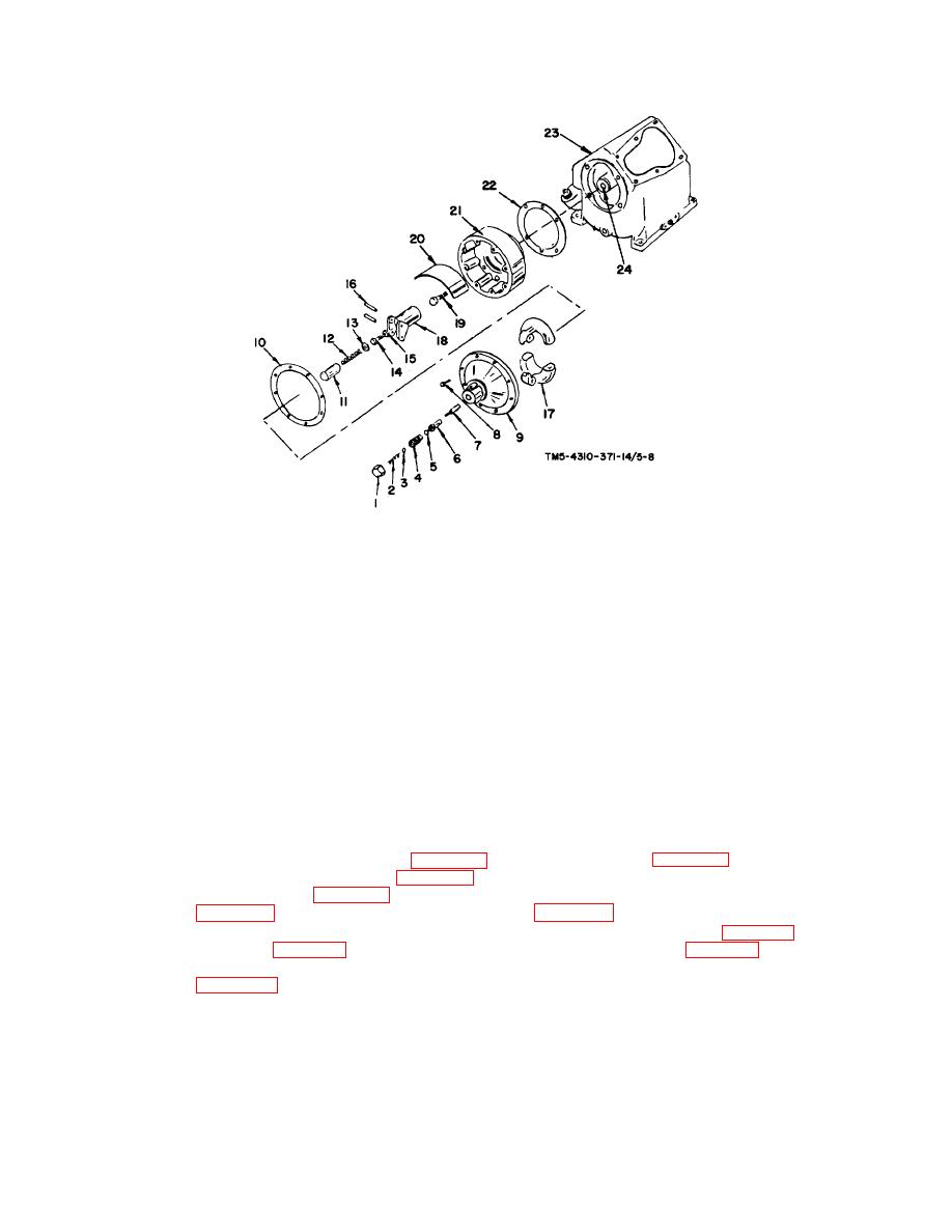
FIGURE 5-8. RELEASE VALVE ASSEMBLY AND GOVERNOR
(a) Install upper governor housing (figure 5-8, item 21) to crankcase (figure 5-8, item 23) leaving out the
governor housing gasket set (figure 5-8, item 22). Attach the housing to the crankcase with one hex
steel cap screw (figure 5-8, item 19) at the top and one at the bottom. Be sure the main bearing
(figure 5-8, item 24) fits properly in the housing (figure 5-8, item 21). Set the two attaching screws
finger tight. Use a feeler gage, measure the gap between the housing (figure 5-8, item 21) and
crankcase (figure 5-8, item 23) at the top and bottom of the housing (figure 5-8, item 21). Average
the two dimensions and add 0.005 inch (0.0127 cm). This will determine the selection of gaskets
Proper adherence to this procedure will minimize crankshaft end play.
5-30


