TM 5-4310-375-14
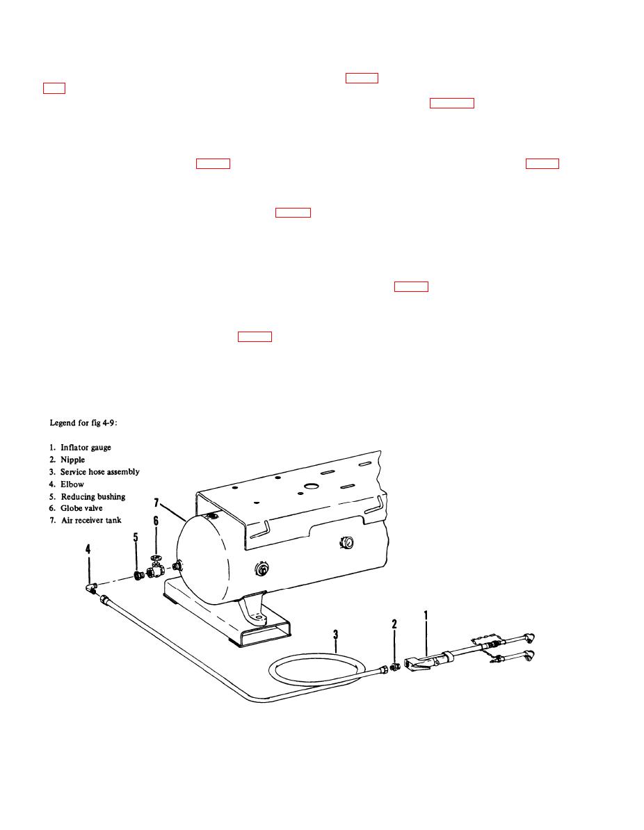
4-27. Inflator gauge. When advised of malfunction of inflator gauge (1, fig 4-9) by operator/crew, close globe valve (6, fig
4-9), relieve pressure in hose; then, unscrew the gauge (1) from end of air service hose nipple (2) and replace with new gauge.
Screw the new gauge (1) onto air service hose nipple (2) and again inspect in accordance with para 3-13.a.
4-28. Air service hose. When advised of any air service hose damage by operator/crew, replace air service hose assembly
as follows:
a. Removal. Close globe valve (6, fig 4-9), relieve pressure in hose; then, unscrew and remove inflator gauge (1, fig 4-9)
and nipple (2) from end of air service hose (3). Disconnect hose assembly from elbow (4). Discard a damaged hose assembly
(3) to avoid possible injury from the use of a defective hose.
b. Replacement. Replace damaged hose assembly (3, fig 4-9) with a new assembly. Attach hose to elbow (4) and
install nipple (2) and inflator gauge (1) on other end. Coil hose assembly on hanger provided on air receiver saddle
until ready for use.
4-29. Gobe valve. When notified of defective globe valve by operator/crew, replace as follows:
a. Removal. Stop the unit and drain air receiver. Disconnect air service hose (3, fig 4-9) at elbow (4). Unscrew and
remove elbow (4) and reducing bushing (5) from globe valve (6), unscrew and remove globe valve (6) from close nipple in end
of receiver tank (7). Discard defective globe valve.
b. Replacement. Screw new globe valve (6, fig 4-9) onto close nipple in tank (7). Position globe valve handle in
up position for easy access. Install reducing bushing (5) in globe valve (6), install elbow (4) and attach air service hose
(3) to elbow (4).
Figure 4-9. Air discharge system
4-24


