TM-5-4310-389-14
b.
Locked Rotor Test.
1.
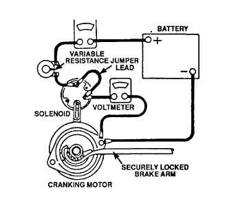
Perform locked rotor test as follows (figure 4-59).
a)
Lock clutch so that it cannot rotate.
b)
Connect starter motor in series with fully charged 12-volt battery, ammeter (1200 amp capacity), and
high current capacity variable resistance.
c)
Connect voltmeter from motor starter solenoid terminal to motor frame.
d)
Install jumper between motor battery and starter solenoid terminals.
e)
When 5 volts are applied, current should fall between 1050 (minimum) and 1100 (maximum) amps.
2.
When test is complete, and if no further disassembly is required, proceed as follows:
a)
Remove test equipment.
b)
Reinstall starter motor.
c)
Reconnect battery cables.
d)
Remove OUT-OF-SERVICE tag from control panel.
Figure 4-59. Locked Rotor Test Connections
4-86

