TM-5-4310-389-14
23.
If commutator bars are not completely burned, resolder leads in riser bars and turn commutator in lathe.
Undercut insulation between bars to 1/32-inch (0.5 mm).
24.
Use test lamp and prods to check for grounds in armature. If lamp lights when one test prod is placed on the
armature core or shaft, then armature is grounded.
25.
Use test lamp to check field coils for grounds and opens, as follows:
a)
To check for grounds, disconnect field coil ground connections. Connect one test prod to field frame and the
other prod to the field connector. If lamp lights, then field coils are grounded.
b)
To check for opens, connect test prods to ends of field coil leads. If lamp does not light, then field coils are
open.
26.
If field coils need to be removed, be careful to avoid grounding or shorting coils when replacing. Refer to
reassembly procedures.
27.
Coat the armature shaft pinion drive splines with a thin coat of grease (MIL-G-21164).
28.
Place collar on armature shaft with cupped surface facing snap ring groove.
29.
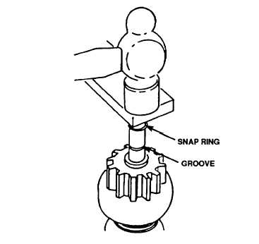
Place snap ring on end of shaft. With piece of wood on top of it, force snap ring over shaft with a light hammer
blow. Then slide snap ring down into groove (figure 4-61).
Figure 4-61. Starter Drive Snap Ring Installation
4-89


