TM 5-4310-393-14
g.
Check that each valve head diameter is not less than 1.193 inch (30.3 mm).
h.
Replace the cylinder head If any of the following conditions exist If the cylinder contact surface is
roughened, warped, and cannot be repaired; the valve seats are so worn that recutting is no longer possible, if contact
surface for cylinder head cover is rough or damaged; or if there are cracks between the valve seats
D.
Install.
1.
Installing the Inspected Components.
a.
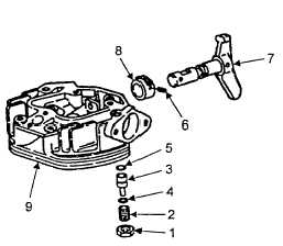
Install pinion (Figure 5-23, Item 8) In
cylinder head (9). Gear teeth go toward the inside and
no-teeth area of the pinion at the bottom.
b.
Insert
decompression
shaft
(7)
through cylinder head (9) and into pinion (8).
c.
Align
holes
in
pinion
(8)
and
decompression shaft (7) d Install roll pin (6).
e.
Install new preformed packing (5) on
pin (3)
FIGURE 5-23. DECOMPRESSION MECHANISM
f.
Install 10 spring plates (4) on pin (3). The spring plates must be installed In five sets with concave
sides together to create spring action.
g.
Install pin (3) with assembled preformed packing (5) and spring plates (4) into cylinder head (9).
h.
Rotate decompression shaft (7) to horizontal position.
I.
Install threaded pin (2) and tighten until snug Shaft must be free to turn but not move with vibration.
j.
Secure lock nut (1).
CAUTION
Do not scratch the cylinder head
sealing surface. Scratches will cause
poor sealing of cylinder head and
cylinder surfaces.
k.
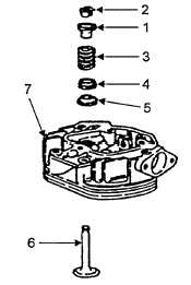
Insert valve (Figure 5-24, Item 6)
into cylinder head (7).
I.
Install cap (5), washer (4), valve
spring (3) and cup (1).
m.
Press down cup (1) and install
collets (2)
FIGURE 5-24. REASSEMBLE VALVES
5-21


