TM 5-4310-451-14
5-64. BLOWER ASSEMBLY REPAIR (Con’t)
35.
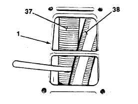
Turn blower housing (1) upside down and place
0.002 in. (0.051 mm) feeler gage between lobes
of rotors (37 and 38). Turn rotors while gage is
in place. Rotors must move freely.
36.
Remove feeler gage.
BOTTOME VIEW
NOTE
To Increase or decrease gap between trailing edge of right rotor lobe and leading edge of left rotor
lobe, perform steps 37 through 41.
37.
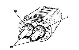
Install puller tool on gear (8) using two Y6 -24
UNC x 1I1 in. screws.
38.
Install puller tool on gear (18) using three Y16 -
24 UNC x 1)1 in. screws.
39.
Place clean rag between lobes of rotors.
40.
Tighten two screws (19) evenly and remove
gears (8 and 18).
TA705102
5-231


