TM 5-4310-451-14
5-73.
ALTERNATOR TESTING AND REPAIR (Con’t).
4.
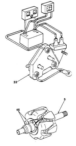
Connect alternator regulator (33) and test lamp
as shown.
5.
Observe battery polarity. Test lamp should be
on.
6.
Turn on fast charger and slowly Increase charge
rate. Observe voltmeter. Test lamp should go
out at alternator regulator (33) setting. Alternator
regulator setting should be a minimum of 27.8
volts and a maximum of 28.2 volts
7.
Remove test lamp and disconnect voltmeter and
fast charger.
8.
Using self-powered test light or ohmmeter,
check for continuity between slip rings (46). If
continuity Is not present, replace rotor assembly.
9.
Using self-powered test light or ohmmeter,
check for continuity between each slip ring (46)
and rotor shaft (5). If there is continuity, replace
rotor assembly.
10.
Check for rotor assembly short circuits and
extreme resistance by connecting a battery and
ammeter in series with edges of two slip rings
(46). Ammeter reading at 700F (21 °C) should
be 4.5-5.0 amps. If ammeter reading is not
within specification, replace rotor assembly.
TA705161
5-295


